


Introduction – Bridging the Gap Between Business Intent and System Behavior
This guide provides a disciplined, four-stage workflow for requirements engineering: moving from a raw Problem Description to a contextual Use Case Diagram, refining it with a textual Use Case Description, and finally detailing the logic with an Activity Diagram. Each stage serves a distinct purpose, and together they form a traceable chain of evidence from business intent to executable design. Whether you are a business analyst seeking clarity, a developer validating assumptions, or a team lead establishing documentation standards, this framework will help you capture requirements accurately, communicate them effectively, and reduce costly rework before a single line of code is written.
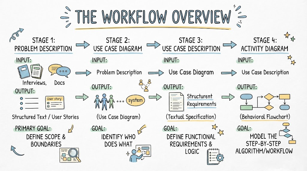
1. The Workflow Overview
| Stage | Input | Output | Primary Goal |
|---|---|---|---|
| Problem Description | Stakeholder interviews, docs | Structured Text / User Stories | Define scope and boundaries |
| Use Case Diagram | Problem Description | Visual Context Map | Identify Who does What |
| Use Case Description | Use Case Diagram | Textual Specification | Define functional requirements & logic |
| Activity Diagram | Use Case Description | Behavioral Flowchart | Model the step-by-step algorithm/workflow |
2. Phase I: Problem Description
Before drawing, you must structure the chaos. A raw problem statement is often ambiguous.
Key Concepts
-
Domain Vocabulary: Establish a ubiquitous language (e.g., “Customer” vs. “Client”, “Order” vs. “Purchase”).
-
Scope Boundary: Explicitly state what is IN and OUT of scope.
-
Pain Points vs. Solutions: Separate the current problem from the proposed technical solution.
Best Practices
-
✅ Use Active Voice: “The Clerk verifies the ID” not “The ID is verified.”
-
✅ Identify Triggers: What starts the process? (Time-based, Event-based, User-initiated).
-
❌ Avoid UI Details: Do not mention buttons, screens, or databases in the problem description. Focus on intent.
Example Scenario
Raw: “We need a way for people to return books. Sometimes they are late and owe money. Librarians have to check if the book is damaged too.”
Structured: “A Library Member initiates a Book Return. The system must calculate potential Late Fees based on the due date. A Librarian must inspect the physical condition of the book. If damaged, a Damage Fee is applied. The member’s account is updated upon completion.”
3. Phase II: Use Case Diagram
This diagram defines the functional scope and actor interactions. It is a context map, not a flowchart.
Key Concepts
-
Actor: External entity (human or system) interacting with the system.
-
Use Case (Ellipse): A discrete unit of functionality that delivers value to an actor.
-
Include (
<<include>>): Mandatory sub-behavior (e.g., “Login” is always required). -
Extend (
<<extend>>): Optional/Conditional behavior (e.g., “Apply Discount” only if eligible). -
Generalization: Inheritance for actors or use cases (e.g., “Admin” extends “User”).
PlantUML Example
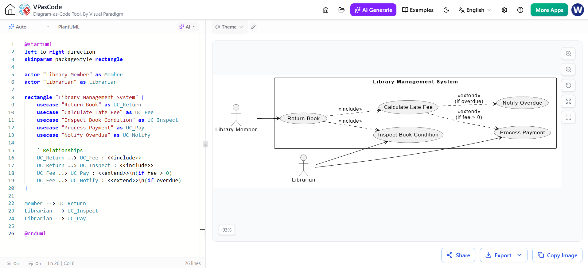
@startuml
left to right direction
skinparam packageStyle rectangle

actor "Library Member" as Member
actor "Librarian" as Librarian

rectangle "Library Management System" {
    usecase "Return Book" as UC_Return
    usecase "Calculate Late Fee" as UC_Fee
    usecase "Inspect Book Condition" as UC_Inspect
    usecase "Process Payment" as UC_Pay
    usecase "Notify Overdue" as UC_Notify

    ' Relationships
    UC_Return ..> UC_Fee : <<include>>
    UC_Return ..> UC_Inspect : <<include>>
    UC_Fee ..> UC_Pay : <<extend>>\n(if fee > 0)
    UC_Fee ..> UC_Notify : <<extend>>\n(if overdue)
}

Member --> UC_Return
Librarian --> UC_Inspect
Librarian --> UC_Pay

@enduml
Guidelines & Best Practices
-
✅ User Goal Technique: Name use cases with Verb + Noun (e.g., “Submit Order”, not “Order Screen”).
-
✅ Keep it High-Level: One bubble = one complete user goal. Don’t model CRUD operations individually unless they are distinct business goals.
-
❌ No Sequencing: Use case diagrams do NOT show time order. Do not connect use cases with arrows to imply flow (except include/extend).
-
❌ Avoid Functional Decomposition: Don’t break “Return Book” into “Scan Barcode”, “Update DB”, “Print Receipt”. Those belong in Activity Diagrams.
4. Phase III: Use Case Description
This textual artifact adds the detail that the diagram cannot convey. It serves as the contract between business and dev.
Standard Template
| Field | Description |
|---|---|
| UC Name & ID | Unique identifier |
| Primary Actor | Who initiates this? |
| Preconditions | State required before start (e.g., “User is logged in”) |
| Postconditions | Guaranteed state after success (e.g., “Inventory updated”) |
| Main Success Scenario | Happy path steps (numbered list) |
| Extensions/Alt Flows | Error handling, conditional branches |
| Business Rules | Specific constraints/calculations |
Example Snippet
UC-05: Return Book
Precondition: Book exists in system; Member account active.
Main Flow:
Librarian scans book ISBN.
System retrieves loan record.
Librarian confirms physical inspection passed.
System marks book as “Available”.
System displays confirmation.
Extension 3a (Book Damaged):
Librarian selects “Report Damage”.
System prompts for damage type/photo.
System adds Damage Fee to member account.
Resume Main Flow at step 4.
Best Practices
-
✅ Number Steps Clearly: Makes referencing in extensions easy (“Resume at step 4”).
-
✅ Black Box Perspective: Describe what the system does, not how (no SQL queries, no API endpoints).
-
❌ Don’t Repeat the Diagram: The description adds logic, it doesn’t just restate the bubble name.
5. Phase IV: Activity Diagram
This translates the Use Case Description into a visual behavioral model. It shows control flow, data flow, concurrency, and decisions.
Key Concepts
-
Action Node (Rounded Rect): Atomic step/work.
-
Decision Node (Diamond): Conditional branching (if/else).
-
Fork/Join (Thick Bar): Parallel execution and synchronization.
-
Swimlanes (Partitions): Responsibility allocation (Who does what?).
-
Object Nodes: Data artifacts flowing between actions.
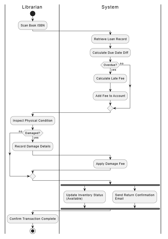
PlantUML Example (Based on UC-05)
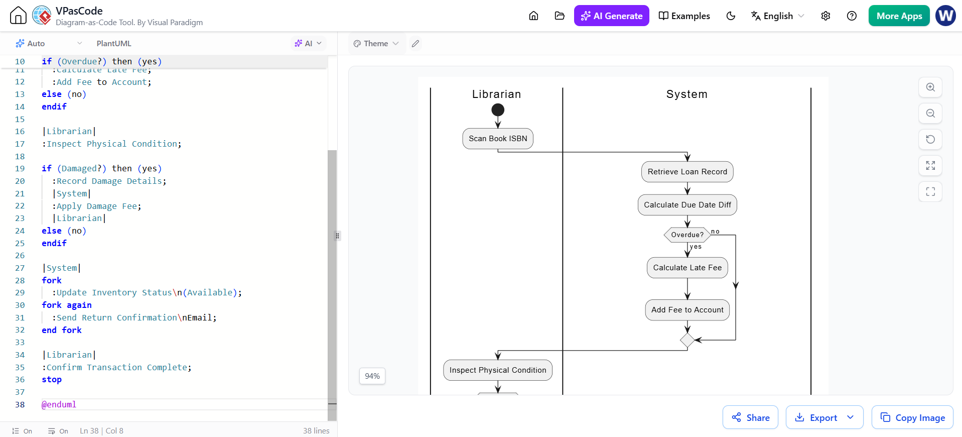
@startuml
|Librarian|
start
:Scan Book ISBN;

|System|
:Retrieve Loan Record;
:Calculate Due Date Diff;

if (Overdue?) then (yes)
  :Calculate Late Fee;
  :Add Fee to Account;
else (no)
endif

|Librarian|
:Inspect Physical Condition;

if (Damaged?) then (yes)
  :Record Damage Details;
  |System|
  :Apply Damage Fee;
  |Librarian|
else (no)
endif

|System|
fork
  :Update Inventory Status\n(Available);
fork again
  :Send Return Confirmation\nEmail;
end fork

|Librarian|
:Confirm Transaction Complete;
stop

@enduml
Guidelines & Best Practices
-
✅ Use Swimlanes: Always clarify responsibility. If everything is in one lane, you’re missing organizational insight.
-
✅ Match the Text: Every action node should trace back to a step in the Use Case Description.
-
✅ Model Exceptions Visually: Show error paths merging back to main flow or terminating gracefully.
-
❌ Don’t Model Code Logic: Avoid loops like
for(i=0; i<n; i++). Model business iteration: “For each item in cart…” -
❌ Avoid Over-complexity: If a diagram has >15 nodes, consider decomposing into sub-activities.
6. Cross-Phase Consistency Checklist
Before finalizing, verify alignment across all artifacts:
| Check | Question |
|---|---|
| Terminology | Is “Late Fee” called the same thing in Problem, UC Diagram, Description, and Activity Diagram? |
| Completeness | Does every Extension in the Description have a corresponding Decision Node in the Activity Diagram? |
| Actor Alignment | Do swimlane headers match the Actors defined in the Use Case Diagram? |
| Scope Adherence | Did any implementation details (DB tables, APIs) leak into the Problem Description or UC Diagram? |
| Traceability | Can you point to the exact requirement source for every action in the Activity Diagram? |
Summary of Golden Rules
-
Problem → Scope → Behavior → Detail: Never skip the problem structuring phase.
-
Diagrams Communicate, Not Decorate: If a diagram doesn’t clarify ambiguity, delete it.
-
Text and Graphics Are Complementary: Use Case Diagrams show context; Descriptions show requirements; Activity Diagrams show logic. You need all three.
-
Iterate: Expect to update the Activity Diagram when writing the Description reveals missing steps. This is normal and healthy.
-
Stakeholder Validation: Walk through the Activity Diagram with the actual Librarian/User. They will spot workflow errors that developers never see.
Related posts:
 UML Diagram Generators vs. Full Modeling Platforms: Why One Isn’t Enough
 The Art of Problem Description: From Traditional Requirements to AI Prompt Engineering
 The Modern Modeler’s Guide: Activity Diagrams with VPasCode & AI
Why UML Remains Relevant in the AI Era: Visual Paradigm, Diagram-as-Code, and Modern Agile
The Modern Modeler’s Guide: Activity Diagrams with VPasCode & AI
Why UML Remains Relevant in the AI Era: Visual Paradigm, Diagram-as-Code, and Modern Agile
