Introduction
BPMN diagrams should make a process easier to understand—not force readers to decode a dense routing rule. A Complex Gateway can express sophisticated conditions for splitting or synchronizing paths, but its flexibility may obscure what the process actually does. That can make a diagram harder for business stakeholders to review, maintain, and implement.
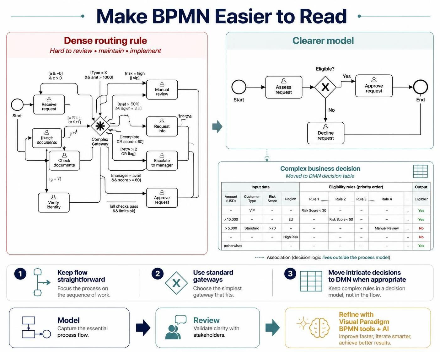
A clearer approach is to model straightforward flow with standard BPMN gateways, and move intricate business decisions into a separate decision model such as DMN when appropriate. This guide explains the key concepts, shows practical alternatives, and outlines a workflow for developing and refining models with Visual Paradigm’s BPMN tools and AI.
Key concepts
Complex Gateway. A BPMN gateway used when the conditions for activating outgoing paths or synchronizing incoming paths do not fit the simpler gateway patterns. Its behavior depends on a defined expression or condition. It can be useful, but a diagram becomes difficult to read when the logic is implicit, lengthy, or unfamiliar to its audience.
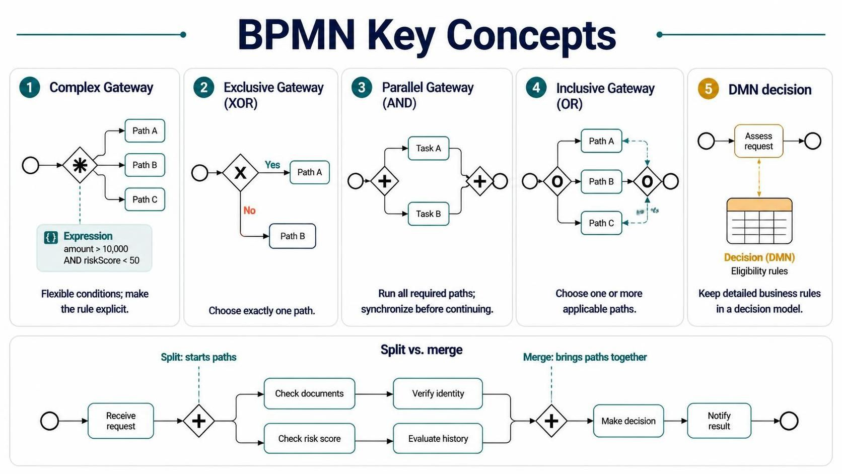
Exclusive Gateway (XOR). Routes a process down one outgoing path. Use it for a mutually exclusive choice, such as approving or rejecting an application.
Parallel Gateway (AND). Activates all outgoing paths, and can synchronize parallel paths before the process continues. Use it when multiple activities must happen, not when a business rule selects among alternatives.
Inclusive Gateway (OR). Activates one or more outgoing paths based on conditions. Use it when several options may apply at once, but not necessarily all of them.
DMN decision. Decision Model and Notation provides a way to represent decision logic separately from the process flow. A BPMN process can invoke a decision and then route according to its result. This helps keep operational steps in BPMN and detailed business rules in a decision model.
Split versus merge. A split determines which paths begin; a merge brings paths together. Their behavior should be designed intentionally. For example, a parallel split needs synchronization of the active parallel paths before work proceeds beyond the merge.
Why avoid Complex Gateways in many business diagrams?
The main issue is not that Complex Gateways are invalid. It is that their logic may be difficult for readers to infer from the diagram. If someone needs to inspect a specialized expression or ask the model’s author how the gateway works, the model may not be communicating clearly.
Complex gateway logic can also combine two distinct concerns:
-
Process flow: What activities happen, and in what order?
-
Business decision: Which outcome applies, given the data and rules?
Keeping these concerns distinct makes the diagram easier to discuss and change. A business rule may evolve without changing the process’s overall structure; conversely, a process may change while the decision policy remains intact.
Choosing a clearer modeling pattern
Use this quick guide to select a starting point:
| Situation | Typical pattern | Example |
|---|---|---|
| Exactly one outcome is selected | XOR gateway | Approve or reject |
| All required activities happen | AND gateway | Run credit and fraud checks |
| One or more optional activities may apply | Inclusive gateway | Notify one or more relevant teams |
| Many detailed rules determine an outcome | DMN decision, followed by BPMN routing | Determine a claim outcome from policy data |
These are modeling patterns, not automatic substitutions. The correct choice depends on what the business means and how paths should behave at runtime.
Example 1: Replace a complicated routing rule with XOR
Suppose a service request is classified into exactly one of three outcomes: standard, urgent, or not eligible.
A clear BPMN structure is:
-
Receive the service request.
-
Assess the request.
-
Use an XOR gateway with clearly labeled, mutually exclusive conditions:
-
[eligible and standard]→ Schedule standard service -
[eligible and urgent]→ Escalate for urgent service -
[not eligible]→ Notify requester
-
-
Continue or end each path as appropriate.
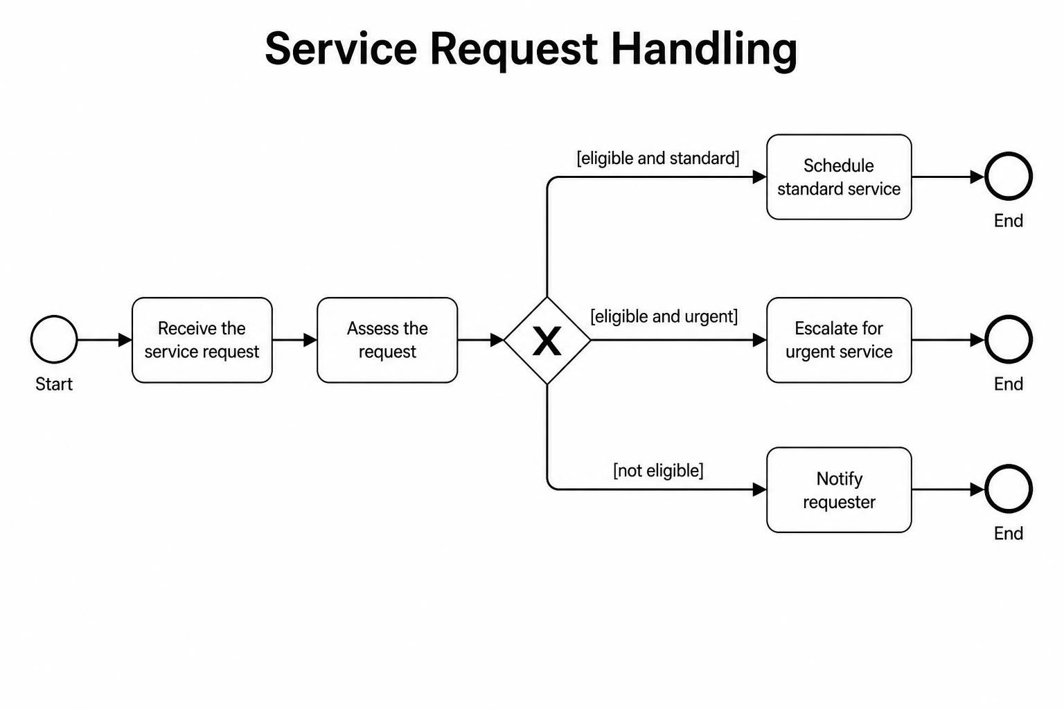
Define what happens if none of the stated conditions match—for example, with a default path to manual review. The conditions should be complete and should not overlap if the intention is to select only one path.
Example 2: Replace an unclear “do some checks” rule with AND
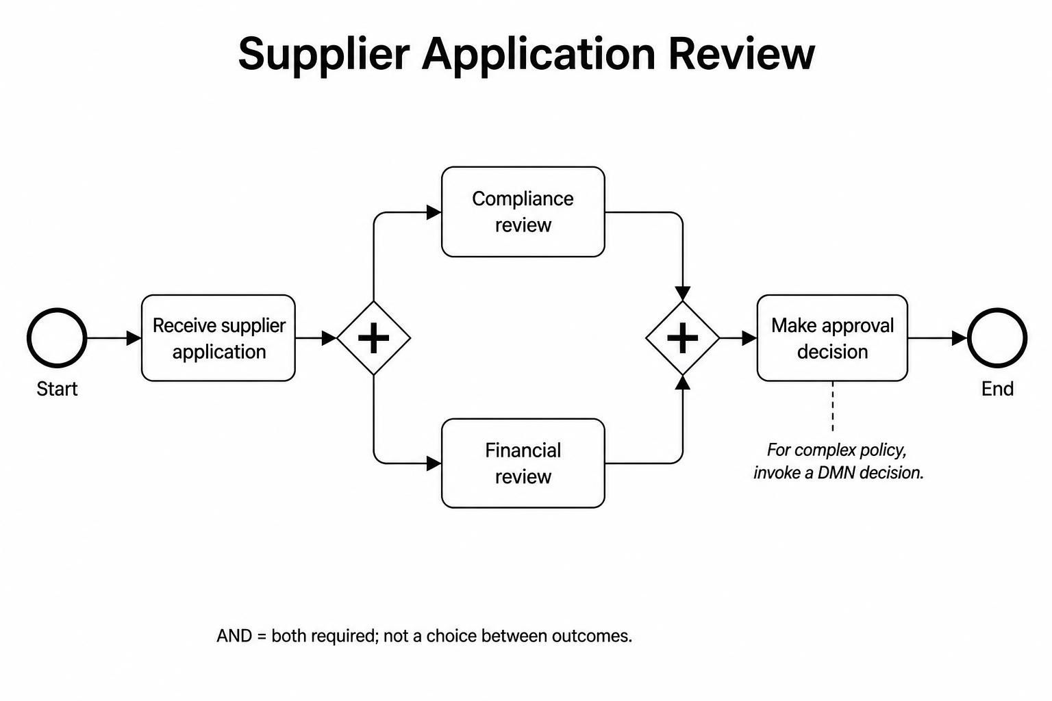
Suppose every new supplier must pass both a compliance review and a financial review. These are independent tasks and both must finish before the supplier can be approved.
A typical model is:
-
Receive supplier application.
-
Use an AND gateway to start the compliance review and financial review in parallel.
-
Use an AND gateway to synchronize the two completed paths.
-
Make the approval decision, or invoke a DMN decision if the approval policy is more involved.
The AND gateway communicates that both checks are required. It should not be used merely because there are multiple possible outcomes.
Example 3: Use DMN for detailed policy rules
Imagine a refund decision depends on product condition, purchase date, customer tier, and refund amount. Listing every combination as a web of gateways can make the process difficult to read and maintain.
Instead:
-
BPMN collects or retrieves the relevant information.
-
The process invokes a DMN decision such as Determine Refund Outcome.
-
The decision returns a result, for example:
-
automatic_refund -
manual_review -
decline
-
-
An XOR gateway routes the process based on that result.
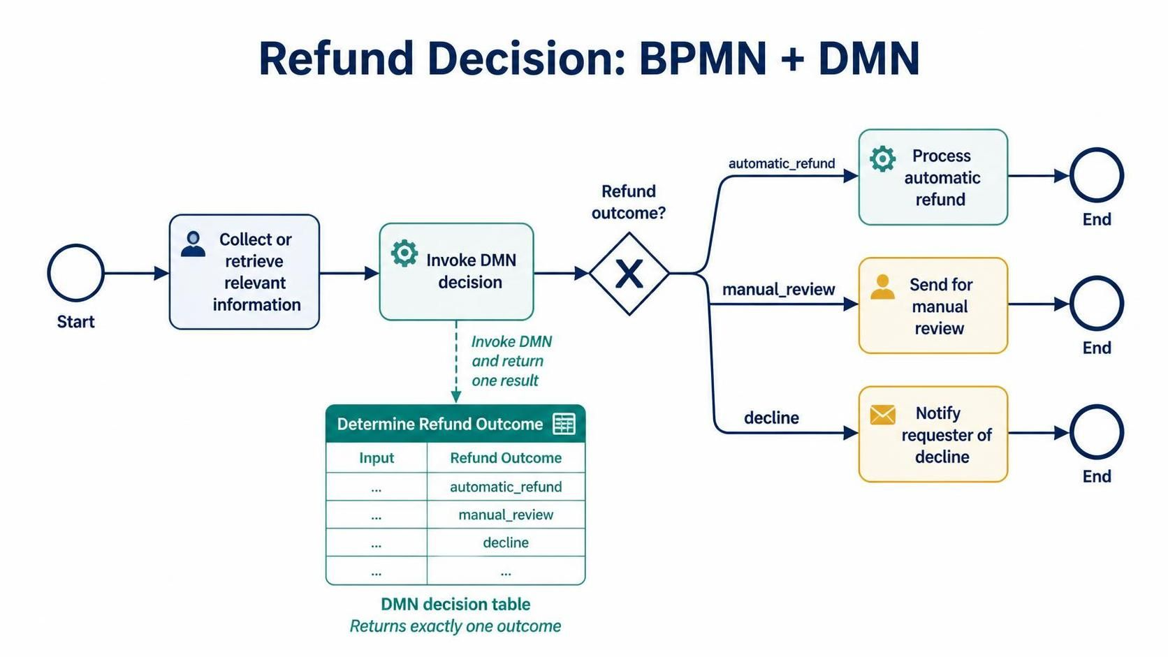
The DMN table can document the inputs, rules, and outcomes, while the BPMN diagram shows the work that follows each outcome. The rule owners should review the decision table, including how it handles missing or conflicting inputs.
A practical modeling workflow
-
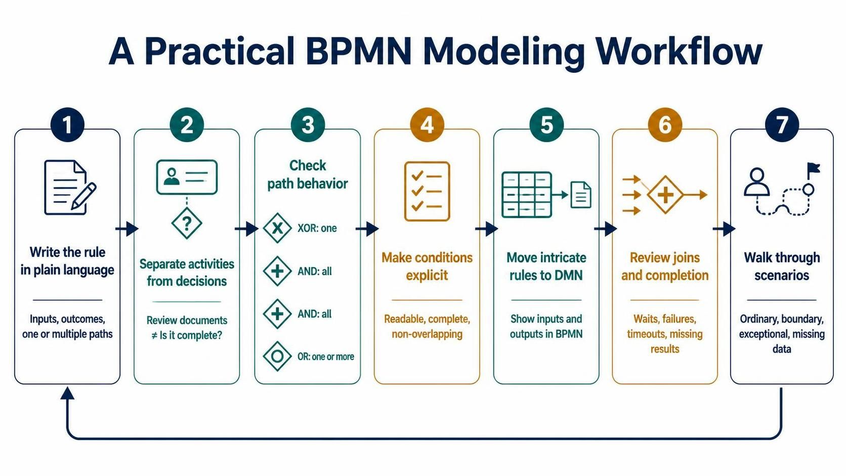
Write the rule in plain language. State what information is considered, which outcomes are possible, and whether more than one path can be taken.
-
Separate activities from decisions. “Review documents” is an activity; “Is the application complete?” is a decision.
-
Check whether paths are mutually exclusive. If exactly one path should run, consider XOR. If all paths should run, consider AND. If any combination of paths may run, consider whether inclusive routing is appropriate.
-
Make conditions explicit. Label outgoing flows with business-readable conditions. Check that conditions cover the intended cases and do not overlap unexpectedly.
-
Move intricate rules to DMN when that improves clarity. Keep the BPMN model focused on process sequence and handoffs; make the decision’s inputs and outputs visible at the point where it is used.
-
Review joins and completion behavior. Confirm what the process must wait for before continuing, and what happens when a path fails, times out, or cannot produce a result.
-
Walk through scenarios. Test ordinary, boundary, exceptional, and missing-data cases with stakeholders.
Using Visual Paradigm BPMN Tool + AI
Visual Paradigm’s AI diagram-generation features can help turn a written process description into an editable BPMN draft. Its BPMN tooling also supports manual modeling and refinement. Treat AI output as a starting point: generated gateways and flow conditions still need to be checked against the actual business rules.
A useful workflow is:
-
Describe the process in chronological order. Name the roles, activities, decision points, conditions, and outcomes. A specific narrative gives the AI less room to guess.
-
Generate a first draft. Use Visual Paradigm’s AI BPMN generation workflow to create a diagram from the description. The available interface and options may vary by product version.
-
Inspect every gateway. Ask whether each one represents a mutually exclusive choice, parallel work, multiple conditional paths, or an event race. Replace unclear logic with the appropriate standard pattern where possible.
-
Refine labels and conditions. Make flow labels understandable to business reviewers, and ensure the logic is complete. Do not assume an AI-generated path condition correctly captures a policy.
-
Extract complex policy rules. If the routing depends on numerous combinations of business data, document the rule separately and model a decision service or DMN decision where that fits the team’s implementation.
-
Validate with scenarios and stakeholders. Review the diagram using representative cases, including edge cases. Confirm both the intended outcome and the behavior at merges.
-
Keep the diagram maintainable. Use a subprocess or supporting decision model when expanding every detail would overwhelm the high-level process view.
A prompt to start from might be:
Create a BPMN process for a supplier application. Procurement checks whether the application is complete. Incomplete applications are returned to the supplier. Complete applications receive parallel compliance and financial reviews. After both reviews finish, evaluate the results: approved suppliers are onboarded; suppliers with a policy exception go to manual review; rejected suppliers receive a notice. Keep the process flow clear and identify any decision rules that would be better represented separately.
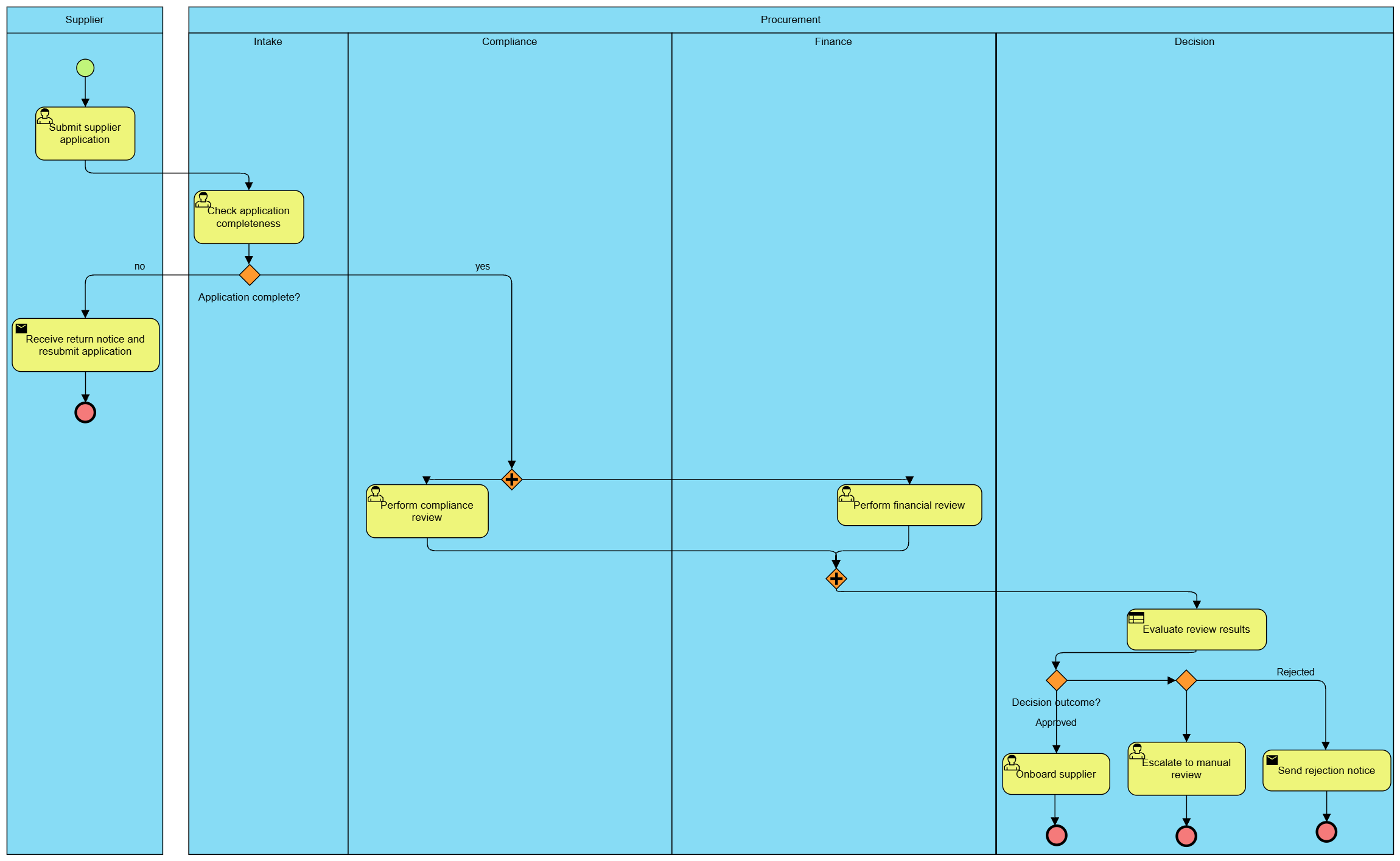
After generation, confirm that the model actually synchronizes both reviews, handles incomplete applications, and routes exceptions as intended.
Common pitfalls
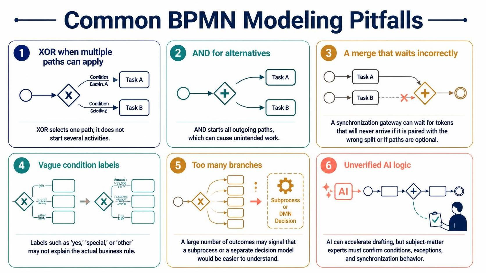
-
Using XOR when multiple paths can apply. XOR selects one path; it does not start several activities.
-
Using AND for alternatives. AND starts all outgoing paths, which can cause unintended work.
-
Using a merge that waits incorrectly. A synchronization gateway can wait for tokens that will never arrive if it is paired with the wrong split or if paths are optional.
-
Hiding conditions in vague labels. Labels such as “yes,” “special,” or “other” may not explain the actual business rule.
-
Creating too many branches. A large number of outcomes may signal that a subprocess or a separate decision model would be easier to understand.
-
Treating AI output as verified logic. AI can accelerate drafting, but subject-matter experts must confirm conditions, exceptions, and synchronization behavior.
Conclusion
Complex Gateways can represent complicated BPMN logic, but they are often not the clearest choice for business-facing process models. Prefer XOR for mutually exclusive choices, AND for work that must happen in parallel, and inclusive routing only when one or more conditional paths may be needed. When rules become detailed or change frequently, separating the decision into DMN can keep the process diagram focused and the policy easier to review.
Visual Paradigm’s BPMN tooling and AI can speed up the first draft and subsequent refinement. The essential work remains careful modeling: make the business rules explicit, verify gateway behavior, and test the process with realistic scenarios before treating the diagram as authoritative.
