


Entity-Relationship Diagrams (ERDs) serve as the foundational blueprint for database design. They translate complex business requirements into a structured visual model that guides the creation of robust data stores. Among the various relationship types found in data modeling, many-to-many relationships often present the most significant challenges. Understanding how to represent and implement these connections is crucial for maintaining data integrity and ensuring query performance.
This guide explores the mechanics of many-to-many relationships within the context of conceptual and logical modeling. We will examine why standard relational structures struggle with direct M:N connections, how to resolve them using associative entities, and the best practices for maintaining a clean schema.
Understanding Cardinality and Relationship Types 🔗
Before tackling complex scenarios, it is essential to review the fundamental cardinalities that define how data entities interact. Cardinality specifies the numerical relationship between records in two connected tables.
- One-to-One (1:1): A single record in Table A relates to exactly one record in Table B. This is common in scenarios like a user profile linked to a single payment method.
- One-to-Many (1:N): A single record in Table A relates to multiple records in Table B. For example, one author writes many books, but each book has one primary author.
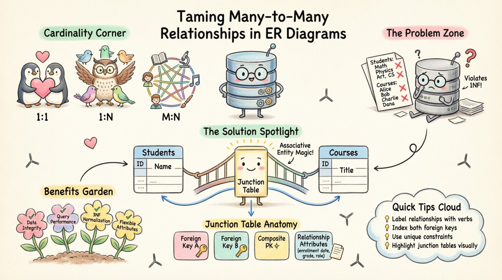
- Many-to-Many (M:N): Multiple records in Table A relate to multiple records in Table B. A classic example is students and courses. One student enrolls in many courses, and one course has many students.
While 1:1 and 1:N relationships map directly to foreign keys in relational database systems, M:N relationships require a more nuanced approach. Relational theory dictates that a relationship is a distinct entity in itself, possessing its own attributes and constraints.
The Core Challenge of Many-to-Many 🧩
In a pure relational model, you cannot place a foreign key in one table to reference multiple rows in another table without creating redundancy or violating normalization rules. If you attempt to store a list of course IDs in a student table (e.g., as a comma-separated string), you violate First Normal Form (1NF). This leads to data anomalies where updating a course name requires changing it in multiple rows, and searching for students in a specific course becomes inefficient.
Therefore, the standard solution involves breaking the M:N relationship into two 1:N relationships. This process transforms the abstract connection into a physical structure that database engines can process efficiently.
Strategy 1: The Associative Entity Pattern 🔗
The most effective method for resolving many-to-many relationships is the creation of an Associative Entity, often referred to as a Junction Table, Bridge Table, or Intersection Table. This table exists solely to link the two parent entities together.
When you introduce an associative entity, the original M:N relationship is decomposed. The relationship between Entity A and the Junction becomes One-to-Many. Similarly, the relationship between Entity B and the Junction becomes One-to-Many.
Structure of an Associative Entity
An associative entity typically contains:
- Foreign Key A: References the primary key of Entity A.
- Foreign Key B: References the primary key of Entity B.
- Composite Primary Key: Often, the combination of Foreign Key A and Foreign Key B forms the unique identifier for the junction record.
- Relationship Attributes: Any data specific to the relationship itself (e.g., enrollment date, grade, role, quantity) belongs here, not in the parent tables.
Consider the scenario of Students and Courses. A direct link implies a student can be in a course multiple times with different grades. By creating a junction table named Student_Course_Enrollment, you capture the grade per student per course.
Visual Representation in ERDs
In your diagram, this appears as two lines connecting the parent entities to the junction entity. The crow’s foot notation (or equivalent cardinality symbols) will show a single line on the parent side and a crow’s foot on the junction side for both relationships.
Strategy 2: Handling Attributes on Relationships 📝
One of the primary reasons for using an associative entity is to store attributes that describe the relationship itself. If a relationship has no attributes, you might consider alternative modeling techniques, but in practice, almost all real-world M:N relationships carry specific data.
- Enrollment Date: When did the student join the course?
- Role: Is the user an instructor, assistant, or student in this context?
- Price: What was the cost associated with this specific transaction between a vendor and a product?
Placing these attributes in the parent tables (Student or Course) would create data redundancy. If a student takes five courses, the enrollment date for the first course would be stored five times if duplicated incorrectly, or it would be impossible to store if not duplicated. The junction table isolates this data cleanly.
Implementation Mechanics and Constraints ⚙️
When moving from the logical model to the physical schema, specific technical considerations ensure data integrity. You must define constraints that prevent invalid data from entering the system.
Foreign Key Constraints
Every column in the junction table that references a parent entity must be defined as a foreign key. This ensures referential integrity.
- If a student record is deleted, the corresponding junction records should be handled. Options include cascading deletes (removing all links) or restricting deletion (if links exist, do not delete the student).
- Similarly, if a course is removed, the links to that course should be managed according to business rules.
Unique Constraints
To prevent duplicate entries in the relationship, a unique constraint is applied to the combination of the two foreign keys. This ensures a student cannot be enrolled in the same course twice unless the system explicitly allows multiple enrollments (e.g., retaking a class), in which case a third key like Enrollment ID would be added.
Indexing Strategies
Performance is critical when querying junction tables. Because these tables are often the bottleneck in joining operations, proper indexing is non-negotiable.
- Indexes should be created on both foreign key columns individually to speed up lookups from either parent side.
- A composite index on both foreign keys is essential for enforcing the unique constraint and optimizing join queries.
Common Pitfalls in M:N Modeling 🚧
Even experienced designers can encounter issues when implementing these patterns. Awareness of common mistakes helps in building more resilient systems.
1. Self-Referencing Many-to-Many
Sometimes, an entity relates to itself in a many-to-many manner. A classic example is an Employee and their Manager. While an employee has one manager, a manager manages many employees. However, in some organizational structures, multiple managers might share responsibility, or employees might be peers collaborating on projects. If a project involves multiple employees working together, an Employee-Project junction is needed. If the relationship is strictly hierarchical, it is 1:N. But if it is a peer-to-peer collaboration, it is M:N.
When modeling self-referencing M:N relationships, the junction table references the same entity table twice.
2. Redundant Foreign Keys
Do not add a foreign key to the parent tables pointing back to the junction table. This creates a circular dependency and violates normalization principles. The junction table is the child; the parents remain independent.
3. Overcomplicating with Multiple Junctions
Occasionally, designers create multiple junction tables for the same relationship to handle different types of data. This fragments the logic. It is better to have one comprehensive junction table with conditional attributes or nullable columns, rather than splitting the relationship across multiple tables unless the data types are fundamentally incompatible.
Normalization and Data Integrity 🛡️
Properly handling M:N relationships directly supports database normalization. By moving relationship attributes to a separate table, you achieve Third Normal Form (3NF).
- 1NF: No repeating groups. The junction table eliminates the need for comma-separated lists.
- 2NF: No partial dependencies. Attributes in the junction table depend on the whole composite key, not just one part.
- 3NF: No transitive dependencies. The attributes describe the relationship, not the entities themselves.
Violating these forms leads to update anomalies. For instance, if you store a course title in the student table, you must update that title in every row where that student took the course. With a junction table, the course title lives in the Course table, and the junction table only holds the link.
Querying Many-to-Many Relationships 📉
Once the schema is established, retrieving data requires joining three tables: Parent A, Junction, and Parent B. This is a standard SQL operation but requires careful construction to avoid Cartesian products.
Example Query Structure
To retrieve all students enrolled in a specific course:
- Join Student table to Junction table on Student ID.
- Join Junction table to Course table on Course ID.
- Filter by the specific Course ID.
Using explicit JOIN syntax (INNER JOIN or LEFT JOIN) is preferred over implicit joins (comma-separated tables in the FROM clause) for clarity and performance.
Performance Considerations
As data volume grows, the junction table can become large. If you frequently need to list all courses for a student, ensure the index on the Student ID in the junction table is optimized. If you need to list all students for a course, the index on the Course ID must be optimized. In high-traffic systems, denormalization might be considered for reporting tables, but the transactional core should remain normalized.
Visual Best Practices for ERDs 🎨
Clarity in documentation is as important as the code itself. When drawing ER diagrams, follow these guidelines to ensure the model is understandable by stakeholders.
- Label Relationships Clearly: Use verbs to describe the relationship (e.g., “Enrolls In”, “Manages”, “Contains”).
- Use Consistent Notation: Stick to one standard, such as Crow’s Foot or Chen Notation, throughout the document.
- Highlight Junction Tables: Visually distinguish associative entities. You might use a different shape or color to indicate that this table is a link, not a core business entity.
- Document Attributes: Ensure attributes specific to the relationship (like “Date Joined”) are visible on the junction table, not hidden.
Comparing Implementation Approaches 📊
Below is a comparison of how different relationship types are handled in a physical schema.
| Relationship Type | Schema Implementation | Primary Key Location | Foreign Key Usage |
|---|---|---|---|
| One-to-One | Foreign key in one table | Either table | Optional or Required |
| One-to-Many | Foreign key in the “Many” table | Primary table | Required in child |
| Many-to-Many | Dedicated Junction Table | Composite (FK1 + FK2) | Required in junction for both |
As the table illustrates, the Many-to-Many relationship stands apart by requiring a dedicated structure. This structural separation is what allows the database engine to manage the complexity without data duplication.
Advanced Considerations: Weak Entities 🌱
In some cases, the associative entity might be considered a weak entity. This occurs when the junction table cannot exist without the parent entities. While the junction table is technically dependent on the foreign keys, it is usually treated as a strong entity in terms of existence. However, if the junction table holds critical business logic that implies existence (e.g., an Order Line Item), it should be treated with the same rigor as a main entity.
If the relationship is optional (e.g., a student might not have selected a course yet), the foreign keys in the junction table should allow NULL values, though this is rare for active links. Typically, the existence of a row in the junction table implies the relationship is active.
Handling Recursive Relationships 🔁
A recursive relationship is a special case where an entity relates to itself. If you model a hierarchy where a department has many sub-departments, and a sub-department can have many sub-departments, this is a recursive 1:N. However, if you model a network of friends where everyone can be friends with everyone, this is a recursive M:N.
The implementation remains the same as a standard M:N, but the foreign keys in the junction table both point to the same parent table. This requires careful naming conventions to distinguish the roles (e.g., Friend_ID_1 and Friend_ID_2).
Moving Forward with Data Architecture 🚀
Designing for many-to-many relationships is a fundamental skill in data architecture. It requires a shift from thinking about static lists to thinking about dynamic connections. By adhering to the associative entity pattern, you ensure your database is scalable, maintainable, and free from the anomalies that plague poorly normalized designs.
Remember that the diagram is a tool for communication. A clear ERD prevents misunderstandings between developers, analysts, and stakeholders. When you encounter a many-to-many situation, pause and ask: “Is there data specific to this connection?” If the answer is yes, a junction table is mandatory. If the answer is no, a simple link suffices.
By applying these advanced strategies, you build a foundation that supports complex queries and flexible business rules. The effort invested in modeling these relationships correctly during the design phase pays dividends in performance and stability throughout the lifecycle of the application.
Continuously review your schema as requirements evolve. Relationships change, and your model should be flexible enough to accommodate new connections without requiring a complete overhaul. This adaptability is the hallmark of a mature data design.

