


Business Process Model and Notation (BPMN) is the standard for visualizing workflows. However, even experienced modelers often create diagrams that look correct but fail during execution. The gap between a visual representation and a functional process often lies in subtle design errors. When a diagram fails, it typically results in process bottlenecks, execution errors, or miscommunication among stakeholders. This guide explores the specific technical reasons why BPMN diagrams fail and provides actionable troubleshooting strategies.
Understanding the underlying mechanics of the BPMN 2.0 specification is crucial. A diagram is not merely a drawing; it is a formal model. If the syntax is correct but the semantics are flawed, the engine cannot interpret the intent. We will dissect common failure points, ranging from gateway logic to data flow errors.
1. Semantic Errors in Gateway Logic ⚙️
The most frequent cause of process failure is incorrect gateway configuration. Gateways control the flow of the process. If the logic is ambiguous, the execution engine may throw an error or behave unpredictably.
Exclusive Gateways vs. Inclusive Gateways
Modelers often confuse Exclusive Gateways (XOR) with Inclusive Gateways (OR). While they look similar, their behavior dictates how paths are activated.
- Exclusive Gateway: Only one outgoing path is taken. The conditions on the outgoing sequence flows must be mutually exclusive. If two conditions are true, the process fails.
- Inclusive Gateway: One or more outgoing paths can be taken. This is used when multiple conditions might be true simultaneously.
Troubleshooting Tip: Review every outgoing path from a gateway. Ensure that the conditions cover all possible outcomes. If a condition is missing, the process may hang waiting for a condition that never evaluates to true.
Parallel Gateways (AND)
Parallel Gateways split the flow into concurrent threads. A common error occurs when threads are not properly joined.
- If a Parallel Gateway splits into two paths, they must eventually meet at a Parallel Join Gateway to synchronize.
- Leaving a thread open without a join point creates a “zombie thread” that continues running indefinitely in the background.
- Mixing Exclusive and Parallel flows without proper synchronization leads to race conditions.
Checklist for Gateways:
- Are all outgoing conditions evaluated?
- Do parallel threads have corresponding join points?
- Are default paths defined for Exclusive Gateways to prevent hanging?
2. Flow Control and Deadlocks 🔗
A well-structured process should never reach a state where no further action is possible, yet the process is not complete. This is known as a deadlock.
Orphaned Paths
An orphaned path occurs when a sequence flow leads to a point where no subsequent activity is defined. This often happens when:
- Deleting an activity without reconnecting the incoming and outgoing flows.
- Creating a path that ends abruptly in the middle of a lane or pool.
- Using a Message Intermediate Event without a corresponding Message Flow.
Implicit End States
Processes must explicitly end. If a flow reaches an activity that has no outgoing sequence flow, the process instance terminates. While sometimes intentional, this is often a mistake. Every process should end with an End Event to signal completion clearly.
Table: Common Flow Errors and Their Impact
| Error Type | Definition | Impact on Execution |
|---|---|---|
| Deadlock | Process waits indefinitely for a condition | Process instance hangs; requires manual intervention |
| Orphaned Flow | Sequence flow leads to no activity | Process instance terminates unexpectedly |
| Unjoined Parallel | Parallel split without a join | Resource leak; multiple instances of subsequent tasks |
| Missing Default | Exclusive gateway without default path | Process hangs if no condition is met |
3. Event Types and Message Flows 📨
Events mark the start, middle, and end of process activities. Misusing event types is a primary source of design failure.
Message Flow vs. Sequence Flow
This is the most critical distinction in BPMN.
- Sequence Flow: Represents the order of activities within a single process or within a single pool. It implies strict control flow.
- Message Flow: Represents communication between two different participants (Pools) or between a Task and a Boundary Event. It implies data exchange, not control.
Common Mistake: Connecting two tasks in different pools with a Sequence Flow. This will cause a validation error. You must use a Message Flow and ensure both tasks are attached to the correct boundaries.
Boundary Events
Boundary Events allow you to define alternative paths when an unexpected event occurs (e.g., an error or a timeout). They must be attached to the Activity they monitor.
- Attachment Point: Ensure the event is attached to the border of the activity, not inside it.
- Interrupting vs. Non-Interrupting: Interrupting events cancel the activity. Non-interrupting events allow the activity to continue while the event is handled. Choosing the wrong one changes the business logic entirely.
4. Data Objects and Variables 📄
Processes manipulate data. If the data model is not integrated into the diagram, the process cannot execute.
Data Input and Output
Tasks should explicitly define what data they consume and produce. However, adding every variable to the diagram can clutter the view. Use Data Objects to represent temporary data storage or references.
- Input Data: Ensure the task has access to the required variables before execution starts.
- Output Data: Ensure the results are stored or passed to the next task via a Sequence Flow.
Global Data Objects
For processes that span multiple pools, use Global Data Objects. These ensure that the data context is shared correctly across the interaction boundaries.
Validation Rule: Every task that requires data must have a clear path for that data to arrive. If a task waits for input that never arrives, the process stalls.
5. Visual Clarity and Naming Conventions 👁️
A diagram that is hard to read is prone to misinterpretation. While visual clarity does not always cause execution errors, it causes adoption errors. Stakeholders must understand the model to trust it.
Labeling Best Practices
- Activity Labels: Use Verb-Noun format (e.g., “Submit Application”, not “Application”).
- Gateway Labels: Clearly state the condition (e.g., “Is Valid?”, “Amount > 1000”).
- Event Labels: Describe the trigger (e.g., “Order Received”, “Error: Timeout”).
Swimlanes and Pools
Swimlanes organize tasks by role or system. Confusion arises when:
- Tasks are placed outside of a Pool or Lane.
- The same role appears in multiple lanes without a clear reason.
- Lanes are too narrow, causing text to be cut off.
Rule of Thumb: Each Lane should represent a distinct responsibility. If a task requires input from another lane, ensure the Message Flow crosses the boundary correctly.
6. Governance and Version Control 📚
Even a perfect diagram can fail if it is not managed correctly. Process models evolve. Without governance, outdated versions cause confusion.
Versioning
Always maintain version history. If a change is made, the previous version should be archived. This prevents the execution engine from running an obsolete model.
- Use clear version numbers (e.g., v1.0, v1.1).
- Document the reason for the change in the version notes.
- Ensure only the latest version is active in the runtime environment.
Validation Standards
Implement a validation process before publishing.
- Syntax Check: Run automated checks to ensure BPMN compliance.
- Semantic Check: Review logic with a subject matter expert.
- Visual Check: Ensure the diagram is clean and readable.
7. Advanced Troubleshooting Scenarios 🔍
Some issues are subtle and require deep inspection.
Event Sub-Processes
Event Sub-processes allow you to define a sub-process that is triggered by an event rather than a sequence flow. A common error is placing a start event inside a sub-process that is already triggered by an event. This creates nested triggers that can confuse the engine.
- Ensure the Sub-Process Start Event is configured correctly.
- Check if the Sub-Process is interrupting the main flow.
Transaction Handling
For tasks that require atomic behavior (all or nothing), use Transaction Sub-processes. If one task fails, the entire transaction rolls back. Failing to define this scope can lead to partial data updates.
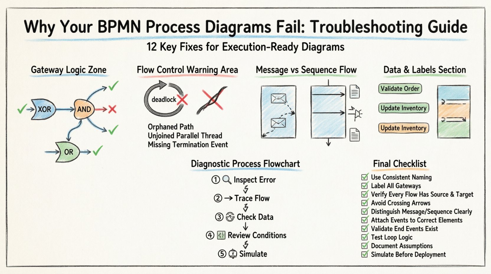
8. Step-by-Step Diagnostic Process 📝
When a process fails, follow this systematic approach to identify the root cause.
- Inspect the Error Message: The engine usually provides a specific error code. Note the task ID or Gateway ID.
- Trace the Flow: Follow the sequence flow backward from the error point to the start.
- Check Data Context: Verify if all required variables exist at the point of failure.
- Review Conditions: Evaluate the boolean logic on all gateways leading to the error.
- Simulate: If possible, run a simulation with sample data to reproduce the failure.
9. Common Pitfalls in Complex Processes 🧩
As processes grow in complexity, the risk of errors increases exponentially.
Nested Loops
Creating a loop inside a loop can lead to infinite execution. Ensure that exit conditions are clearly defined for every loop.
Concurrent Task Assignment
If multiple tasks are assigned to the same person simultaneously, resource contention occurs. Use Parallel Gateways to split tasks, but ensure the join logic aggregates the results correctly.
External System Dependencies
Processes often rely on external systems. If an external call times out, the process must handle the error gracefully. Do not rely on the external system to signal completion; use timeouts or error events.
10. Building a Resilient Model 🛡️
To prevent future failures, adopt a disciplined modeling approach.
- Start Simple: Model the happy path first. Add error handling later.
- Use Templates: Create standard templates for common patterns (e.g., Approval, Notification, Integration).
- Peer Review: Have another modeler review the diagram before publishing.
- Documentation: Keep a separate document explaining complex logic that cannot fit on the diagram.
11. Metrics and Continuous Improvement 📈
Once a process is live, monitor its performance. Metrics can reveal design flaws that were not apparent during modeling.
- Execution Time: If a task takes too long, check for bottlenecks or resource constraints.
- Failure Rate: High failure rates at a specific task indicate a logic error or data quality issue.
- Throughput: Ensure the process can handle peak loads without queuing errors.
Use these metrics to refine the BPMN model continuously. A model is never finished; it is a living artifact that must adapt to changing business needs.
12. Final Checklist for Modelers ✅
Before finalizing any BPMN diagram, run through this comprehensive checklist.
- All Pools and Lanes are defined?
- Every Task has a clear owner?
- Are all Gateways properly joined?
- Is there a default path for Exclusive Gateways?
- Are Message Flows crossing Pool boundaries?
- Are all Start and End Events defined?
- Is the diagram free of crossing lines?
- Are labels descriptive and consistent?
- Is the version number up to date?
- Have data objects been validated?
By rigorously applying these troubleshooting steps and adhering to best practices, you can ensure that your process diagrams are robust, accurate, and ready for execution. The goal is not just to draw a picture, but to define a reliable mechanism for business operations.

