Backend architecture relies on precise documentation to function effectively. Without clear visual representations of how data is stored and how it moves through a system, complexity quickly spirals out of control. Two primary tools dominate the landscape of system design: the Entity-Relationship Diagram (ERD) and the Data Flow Diagram (DFD). While both serve the purpose of modeling, they address fundamentally different questions. One focuses on structure, while the other focuses on process.
Understanding the distinction between these modeling techniques is critical for backend engineers, database administrators, and system architects. Confusing them can lead to schema designs that cannot support the required workflows or workflows that ignore critical data constraints. This guide provides a comprehensive breakdown of when to apply each diagram type to ensure your backend infrastructure remains robust, scalable, and maintainable. 🛠️
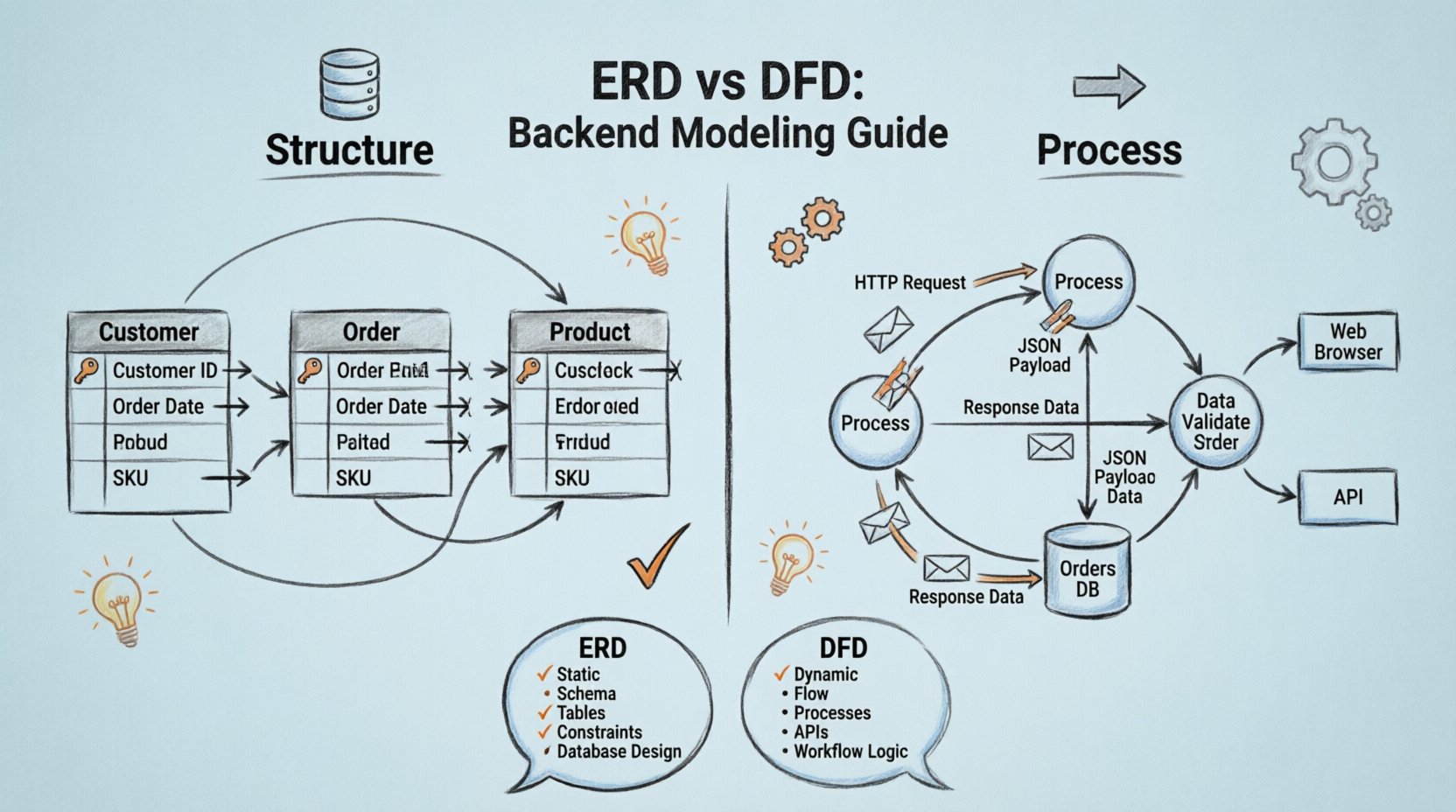
🏗️ What is an Entity-Relationship Diagram (ERD)?
An Entity-Relationship Diagram is a static model. It represents the structure of the data within a database. It answers the question: What data exists, and how is it related to other data? The primary focus is on entities, which are objects or concepts, and the relationships between them. This modeling technique is the foundation for relational database design.
Core Components of an ERD
- Entities: These are the nouns of your system. Examples include Customer, Order, Product, or User. In a physical database, these typically map to tables.
- Attributes: These are the properties that describe an entity. For a Customer entity, attributes might include ID, Name, Email, and Phone Number. These map to columns within a table.
- Relationships: These define how entities interact. They are often represented as verbs. For example, a Customer Places an Order. Relationships define the cardinality of the data, such as one-to-one, one-to-many, or many-to-many.
- Keys: Primary keys uniquely identify an entity instance. Foreign keys link entities together, establishing referential integrity.
Why ERDs Matter for Backend Development
The ERD dictates the schema. When developers write code to interact with a database, they are relying on the constraints defined in this diagram. A well-constructed ERD ensures data integrity. It prevents orphaned records and ensures that relationships are enforced at the database level.
Key considerations when designing an ERD include:
- Normalization: Reducing data redundancy by organizing attributes into logical groups. This typically involves adhering to Normal Forms (1NF, 2NF, 3NF).
- Data Types: Defining the specific type of data (integer, string, timestamp) to ensure efficient storage and retrieval.
- Constraints: Establishing rules such as
NOT NULL,UNIQUE, orCHECKconstraints that the database engine must enforce. - Performance: Identifying which fields require indexing based on query patterns.
If you are designing a new database or refactoring an existing one, the ERD is your primary blueprint. It is the source of truth for the persistent layer of your application.
🔄 What is a Data Flow Diagram (DFD)?
In contrast to the static nature of the ERD, a Data Flow Diagram is a dynamic model. It represents the movement of data through a system. It answers the question: How does data enter, change, and leave the system? It focuses on processes, data stores, external entities, and the flows connecting them.
Core Components of a DFD
- Processes: These are actions or transformations applied to data. A process takes input data, performs a calculation or logic, and produces output. In backend terms, this often maps to a function, service, or API endpoint.
- Data Stores: These represent where data is held at rest. Unlike the database tables in an ERD, data stores in a DFD are abstract locations where data persists between processes. This could be a file, a database, or a queue.
- External Entities: These are sources or destinations of data outside the system boundary. Examples include a Web Browser, a Third-Party API, or a Human Operator.
- Data Flows: These are the arrows showing the direction of data movement. Each flow is labeled with the name of the data packet being transferred.
Levels of DFD Abstraction
DFDs are often created in layers to manage complexity:
- Context Diagram (Level 0): A high-level view showing the entire system as a single process and its interactions with external entities.
- Level 1 Diagram: Breaks the main process into major sub-processes. This provides a functional overview of the system’s major components.
- Level 2 Diagram: Further decomposes specific sub-processes into more granular steps, useful for detailed logic design.
Why DFDs Matter for Backend Development
The DFD maps the logic and flow of your application. It is essential for understanding the lifecycle of data. It helps identify bottlenecks, security vulnerabilities in data transmission, and unnecessary data movement.
Key considerations when designing a DFD include:
- Input Validation: Ensuring data is checked before it enters a process.
- Security: Identifying where sensitive data is exposed or transmitted.
- Asynchronous Processing: Showing where data moves through queues or background jobs rather than immediate responses.
- State Management: Visualizing how data changes state as it moves through the system.
If you are designing an API, a microservice architecture, or a complex data pipeline, the DFD is your primary tool for mapping the logic.
⚖️ Key Differences: ERD vs. DFD
Confusion often arises because both diagrams deal with data. However, their purpose, audience, and output differ significantly. The table below outlines the specific distinctions to help you choose the right tool for the task. 📋
| Feature | Entity-Relationship Diagram (ERD) | Data Flow Diagram (DFD) |
|---|---|---|
| Primary Focus | Data Structure and Relationships | Data Movement and Transformation |
| Time Dimension | Static (Snapshot of Schema) | Dynamic (Sequence of Operations) |
| Key Elements | Tables, Columns, Keys, Constraints | Processes, Flows, Data Stores, Entities |
| Backend Application | Database Design, Schema Migration | API Design, Workflow Logic, Pipelines |
| Output Result | SQL Scripts, Physical Schema | Process Logic, Service Interfaces |
| Complexity Handling | Normalization, Cardinality | Decomposition, Context Boundaries |
🎯 When to Use an ER Diagram
There are specific scenarios where the ERD is the mandatory starting point. Using a DFD in these situations would fail to capture the critical constraints required for data integrity.
1. Initial Database Design
When starting a new project, you must define the storage layer before defining the logic. The ERD allows you to plan the schema. It ensures that all necessary data points are captured and that relationships are logically sound before any code is written.
2. Schema Refactoring
As applications grow, data requirements change. You might need to split a table or merge two entities. An ERD allows you to visualize the impact of these changes on existing relationships. It helps prevent breaking queries that rely on specific foreign key constraints.
3. Complex Query Optimization
When performance issues arise, understanding the data structure is vital. If joins are slow, the ERD helps identify missing indexes or poorly normalized tables. It provides the map needed to tune the database engine.
4. Data Governance and Compliance
Regulations often require knowledge of where data lives and how it is related. An ERD provides a clear inventory of data assets. It helps identify sensitive fields (PII) and how they are linked across the system, which is essential for auditing.
5. Multi-Database Environments
In polyglot persistence architectures where different data is stored in different systems (e.g., SQL for transactions, NoSQL for catalogs), the ERD helps define the logical boundaries of each store. It clarifies which data belongs where.
🚀 When to Use a Data Flow Diagram
The DFD shines when the complexity lies in the logic, not the storage. It is the tool of choice for mapping the behavior of the system.
1. API Design and Documentation
Before writing code for an endpoint, a DFD clarifies what input is needed and what output is returned. It helps define the contract between the client and the server. It ensures that all required data fields are accounted for in the request and response.
2. Microservices Architecture
When breaking a monolith into microservices, the DFD is crucial for defining service boundaries. It shows how data moves between services via APIs or message queues. It helps identify coupling points where services depend too heavily on one another.
3. ETL and Data Pipelines
Data engineering relies heavily on flow. A DFD maps the journey of data from ingestion to transformation to loading. It helps identify where data might be lost, duplicated, or corrupted during transit.
4. Security Auditing
Security teams need to know how data travels. A DFD highlights where data is exposed to external entities or third-party services. It helps identify points where encryption is required or where access controls need to be enforced.
5. Workflow Automation
For systems that trigger actions based on events (e.g., sending an email after an order is placed), the DFD maps the sequence of events. It ensures that all necessary steps are triggered in the correct order.
🔗 Integrating ERD and DFD in Backend Development
In practice, backend development rarely uses one diagram exclusively. The most robust systems utilize both. They complement each other. The ERD defines the container, and the DFD defines the activity within the container.
The Design Workflow
- Define the Domain: Identify the core concepts. This leads to the initial ERD draft.
- Map the Processes: Identify how users interact with these concepts. This creates the Level 0 DFD.
- Refine the Schema: Adjust the ERD based on the requirements found in the DFD. For example, if a process requires frequent searching by a specific field, add an index to the ERD.
- Detail the Logic: Break down the DFD processes into Level 1 and Level 2 diagrams. This defines the API endpoints and service logic.
- Implement and Iterate: As code is written, update both diagrams to reflect reality. This ensures documentation stays current.
Handling Conflicts
Sometimes, the requirements for flow conflict with the requirements for structure. For example, a DFD might suggest a many-to-many relationship for high flexibility, but an ERD might normalize it to reduce redundancy. In these cases, a trade-off analysis is necessary.
- Read-Heavy Systems: Prioritize the ERD for denormalization to speed up reads.
- Write-Heavy Systems: Prioritize the ERD for normalization to minimize write complexity and redundancy.
- High Throughput: Prioritize the DFD for asynchronous processing to handle load spikes.
⚠️ Common Pitfalls to Avoid
Even experienced engineers make mistakes when modeling. Being aware of common traps can save significant time during development.
1. Over-Engineering the ERD
Attempting to predict every future requirement leads to a schema that is too rigid. It is better to design for the current requirements and use migration tools to evolve the schema later. Avoid creating tables for hypothetical features.
2. Ignoring Data Types in the ERD
An ERD is not just about entities; it is about the data types. Choosing the wrong type (e.g., using a string for a date) causes performance issues and storage bloat. Ensure the ERD specifies exact data types.
3. Missing External Entities in the DFD
It is common to forget third-party services. If your system relies on a payment gateway or an email service, these must appear as external entities in the DFD. Forgetting them leads to incomplete integration logic.
4. Circular Data Flows
In a DFD, ensure data flows logically. Circular dependencies between processes can indicate a design flaw or a deadlock situation in the backend logic.
5. Inconsistent Naming Conventions
Use consistent terminology across both diagrams. If the ERD calls a field user_id, the DFD flow should reference User ID. Inconsistency creates confusion for developers reading the documentation.
6. Static DFDs
A DFD that does not account for error handling or retry logic is incomplete. Backend systems must handle failures. Add flows for error messages and rollback processes to the diagram.
📝 Best Practices for Documentation
To maintain the value of these diagrams, follow these maintenance practices.
- Version Control: Treat diagrams as code. Store them in your repository. This allows you to track changes over time and revert if necessary.
- Automate Generation: Where possible, generate ERDs from the actual database schema. This ensures the documentation matches the code. Tools exist to reverse-engineer SQL scripts into visual diagrams.
- Keep it Simple: A diagram that is too complex is useless. Use grouping and decomposition to manage complexity. Don’t show every single API call in a Level 1 diagram.
- Review Regularly: During sprint planning or architecture reviews, update the diagrams. If a feature is added, the diagrams should reflect it.
- Collaborate: Involve developers, DBAs, and product managers in the diagramming process. Different perspectives catch different flaws.
🛠️ Technical Considerations for Backend Teams
When implementing these models, consider the technical stack.
Relational vs. NoSQL
While ERDs are traditionally associated with relational databases, they are still useful for NoSQL. In document stores, the ERD maps to the structure of the document schema. In graph databases, the ERD maps directly to nodes and edges. The principles of relationships remain valid regardless of the storage engine.
Microservices and Distributed Systems
In distributed systems, the DFD becomes even more critical. It must show network boundaries. Data flows across the network introduce latency and security risks. The DFD helps identify where to place caching layers or message brokers to optimize performance.
Event-Driven Architectures
Modern backends often use event streams. The DFD must represent these streams. Instead of direct process-to-process flows, data flows through a bus or broker. The ERD must represent the schema of the events being published and consumed.
📈 Measuring Success
How do you know if your modeling is working? Look for these indicators:
- Reduced Onboarding Time: New developers understand the system faster when diagrams are available.
- Fewer Data Errors: A clear ERD leads to fewer constraint violations in production.
- Clearer API Contracts: A clear DFD leads to fewer misunderstandings between frontend and backend teams.
- Scalability: The architecture supports growth without requiring a complete rewrite of the data layer.
🏁 Final Considerations
Selecting between an Entity-Relationship Diagram and a Data Flow Diagram is not an either-or decision. It is a strategic choice based on the current phase of development. The ERD grounds your system in reality, ensuring data is stored correctly. The DFD guides your system through its purpose, ensuring data is processed effectively.
By mastering both, backend engineers can build systems that are not only functional but also maintainable and scalable. Documentation is an investment. The time spent creating these diagrams pays dividends when troubleshooting, scaling, or refactoring. Keep your models accurate, keep your diagrams clean, and let the structure of your data support the flow of your logic.
Remember, the goal is clarity. Whether you are mapping tables or processes, the ultimate aim is to reduce ambiguity and ensure every stakeholder understands the system architecture. 🚀

