Entity Relationship Diagrams (ERDs) are often dismissed by some as academic exercises or artifacts created solely for documentation compliance. However, for senior developers and architects, an ER diagram is a strategic blueprint that dictates the stability, performance, and maintainability of an application’s data layer. The challenge lies not in drawing boxes and lines, but in navigating the friction between theoretical data modeling and the messy constraints of production environments.
When building systems, you are constantly making trade-offs. A perfectly normalized schema ensures data integrity but may incur performance penalties during complex queries. A denormalized structure speeds up reads but introduces redundancy and update anomalies. The goal is to find the equilibrium where the diagram accurately reflects the business domain without becoming a liability during deployment.
The Dual Nature of Entity Relationship Diagrams 📐
Understanding the lifecycle of an ER diagram requires recognizing that it serves multiple masters. It is not a static image but a living document that evolves alongside the software. There are three distinct layers of abstraction that must be managed separately to avoid confusion between what the data should look like and what it does look like in memory.
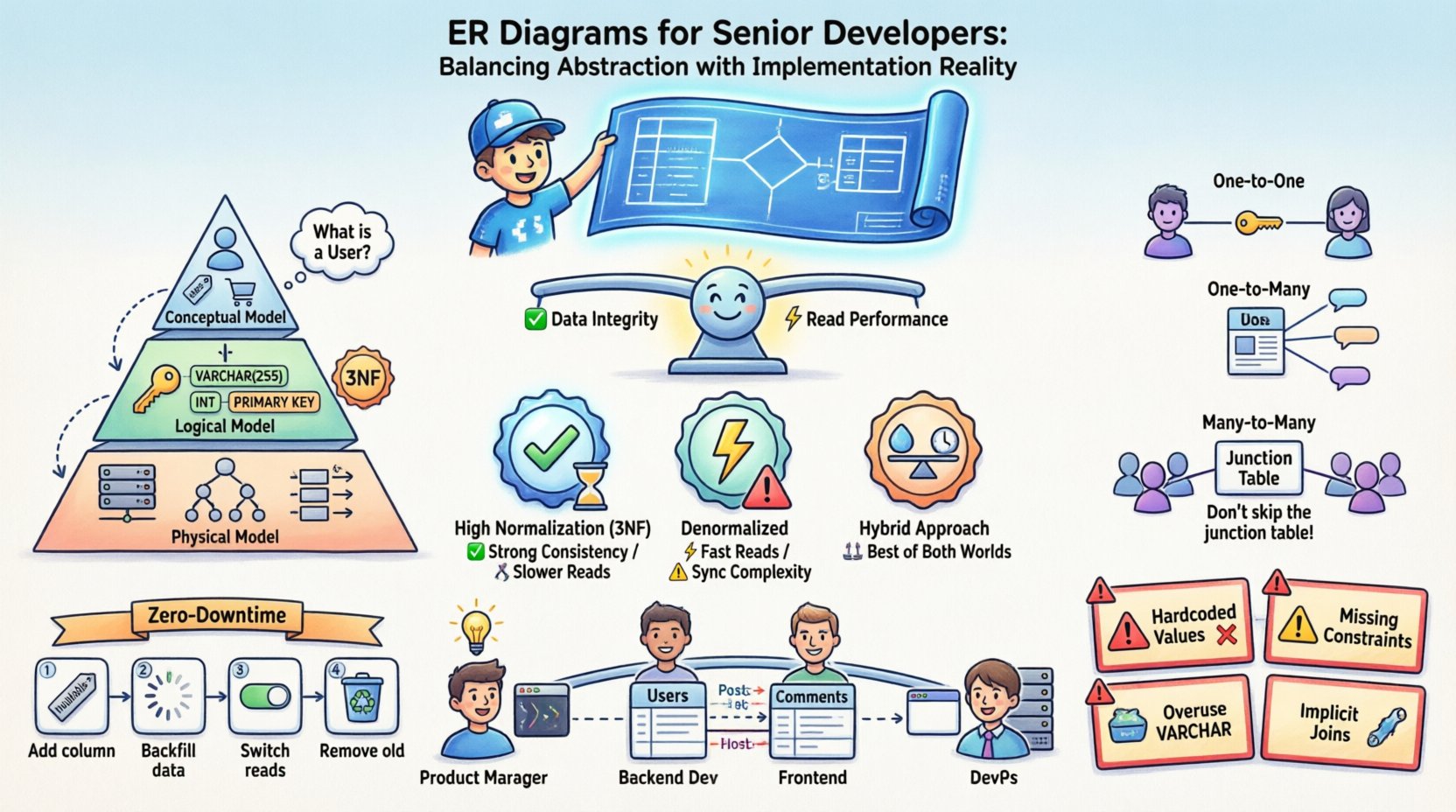
- Conceptual Model: This layer focuses on business entities and their relationships without technical details. It answers questions like “What is a User?” and “How does a User relate to an Order?”. It is technology-agnostic.
- Logical Model: Here, you introduce data types, keys, and normalization rules. You define primary and foreign keys, but you do not yet commit to a specific database engine’s storage engine or indexing strategy.
- Physical Model: This is the implementation reality. It includes table names, column data types, partitioning strategies, indexing, and constraints specific to the target database system. This is where the rubber meets the road.
Confusion often arises when these layers are conflated. A senior developer knows that the physical model is where the bugs hide. A conceptual relationship of “Many-to-Many” must be resolved into specific foreign key constraints in the physical model, often requiring junction tables that do not exist in the original business logic.
Abstraction Layers in Data Modeling 🧩
Managing these layers requires discipline. When a stakeholder requests a feature, they describe it in business terms. The developer must translate this into a logical schema, and finally into a physical schema. Skipping steps here leads to technical debt.
1. Conceptual Modeling: The Business Language
At this stage, the diagram is a communication tool. It ensures that the engineering team and the product team agree on the domain model. If the diagram shows that a “Customer” can have multiple “Addresses”, everyone agrees on that fact before a single line of SQL is written.
2. Logical Modeling: The Rules of Engagement
This is where you apply normalization rules. You determine that a “Customer” should not store their “Address” directly if that address might change frequently and belong to other entities. You introduce normalization to reduce redundancy. However, you also identify which data will be read-heavy and might require denormalization later.
3. Physical Modeling: The Implementation Reality
This is where the database engine’s limitations come into play. You might need to choose between a JSON column and a separate relational table for flexible attributes. You decide on indexing strategies based on query patterns. You might decide to use a specific storage engine that supports faster writes but slower reads.
Normalization Strategies and Performance Trade-offs ⚖️
Normalization is a fundamental concept in database design. It organizes data to reduce redundancy and improve data integrity. However, in high-scale systems, strict adherence to normalization rules can become a bottleneck. Senior developers must understand when to break the rules.
The Cost of Normalization
When you normalize data, you often create more tables. This means more joins when querying. In a distributed system or a high-traffic web application, every join is a potential latency point. If a table is partitioned, joining across partitions can be expensive.
When to Denormalize
Denormalization is the intentional introduction of redundancy to optimize read performance. It is not a mistake; it is a strategic decision. You should consider denormalization when:
- Read operations significantly outweigh write operations.
- Complex joins are causing timeouts or high CPU usage.
- You are building a reporting or analytics layer where real-time consistency is less critical.
- You need to denormalize data for caching layers to reduce database load.
Normalization vs. Performance Matrix
| Strategy | Data Integrity | Write Performance | Read Performance | Maintainability |
|---|---|---|---|---|
| High Normalization (3NF) | High | Fast (less redundancy) | Slower (requires joins) | High (easy updates) |
| Denormalized | Lower (manual sync needed) | Slower (more data to write) | Faster (fewer joins) | Lower (risk of inconsistency) |
| Hybrid Approach | Moderate | Moderate | Moderate to Fast | Moderate (requires clear logic) |
Understanding this matrix allows you to make informed decisions. You do not simply “normalize everything” or “denormalize everything”. You analyze the specific access patterns of your application.
Modeling Complex Relationships 🔗
Relationships are the core of an ER diagram. They define how data entities interact. While One-to-One and One-to-Many are straightforward, Many-to-Many relationships often require careful handling to ensure scalability.
One-to-One Relationships
These are rare in practice but exist. For example, a User profile and a User Profile Settings table. You can implement this by placing a foreign key in one table or splitting the data into two tables. The decision depends on access patterns. If settings are accessed frequently with the profile, keep them together. If they are rarely accessed, separate them to reduce the main table size.
One-to-Many Relationships
This is the most common pattern. A Blog Post has many Comments. The foreign key lives in the “Many” side (Comments). This is efficient for queries that retrieve all comments for a specific post.
Many-to-Many Relationships
A User can follow many Users, and a User can be followed by many Users. This requires an intermediate junction table. This table typically holds the foreign keys of both sides plus any metadata specific to the relationship, such as a timestamp of when the connection was made.
- Do not skip the junction table: It allows you to index the relationship and query efficiently.
- Consider composite keys: The primary key of the junction table might be a combination of the two foreign keys.
- Watch for cardinality: Ensure you handle cases where the relationship is optional versus mandatory.
Schema Evolution and Migration 🔄
One of the hardest parts of being a senior developer is realizing that the ER diagram is never finished. Requirements change, business logic shifts, and data grows. Your schema must evolve without breaking existing functionality.
Versioning the Schema
Never assume a migration is a one-time event. Treat your schema like code. Use version control for your migration scripts. This allows you to roll back changes if a new column causes an issue. It also provides an audit trail of how the data structure changed over time.
Zero-Downtime Migrations
For production systems, downtime is often unacceptable. This requires a phased approach to schema changes:
- Add columns first: Add the new column as nullable. Deploy the code that writes to it.
- Backfill data: Run a background job to populate the new column.
- Switch reads: Update the application to read from the new column.
- Remove old columns: Once the system is stable, drop the old column.
Handling Locks
Adding an index or a constraint on a large table can lock the table, stopping writes. You must use online schema change tools or partitioning strategies to minimize lock duration. Understanding the underlying database engine’s locking mechanism is crucial here.
Common Pitfalls in Production Environments 🚧
Even experienced developers make mistakes when translating ERDs to SQL. Being aware of common pitfalls helps you avoid them before they become critical issues.
- Hardcoded Values: Avoid using `INT` columns to store boolean flags (0/1) without explicit constraints. Use `BOOLEAN` types or enumerated types where supported.
- Missing Constraints: Relying solely on application logic to enforce foreign keys is risky. If a bug allows a bad insert, the data is corrupted. Enforce constraints at the database level.
- Overuse of VARCHAR: While flexible, `VARCHAR` can be slower than fixed-length types like `CHAR` for certain data. Use `CHAR` for fixed-length data like UUIDs or postal codes.
- Ignoring Character Sets: If your application supports international characters, ensure your database and tables are configured to support UTF-8 from the start. Changing this later is difficult.
- Implicit Joins: Avoid queries that join tables without explicit indexes. Always review the query execution plan.
Communication Across Teams 🤝
An ER diagram is a communication tool. It bridges the gap between database administrators, backend developers, frontend developers, and product managers. A clear diagram prevents assumptions.
- For Product Managers: It helps them understand the data requirements for a feature request.
- For Frontend Developers: It clarifies the structure of data they will receive from APIs.
- For DevOps: It informs capacity planning and backup strategies.
If the diagram is unclear, the team will guess. Guessing leads to bugs. A senior developer ensures the diagram is accurate, up-to-date, and accessible to everyone involved in the project lifecycle.
Tools vs. Thinking 💡
There are many tools available to draw ER diagrams. While they are useful for visualization, they should not replace critical thinking. A tool can generate SQL from a diagram, but it cannot understand the business logic behind why a relationship exists.
- Focus on Logic: Spend more time on the whiteboard or in text editors discussing the model than clicking buttons in a drawing tool.
- Validate with SQL: Once the diagram is drawn, write the SQL. If the SQL is confusing, the diagram is likely flawed.
- Keep it Simple: Do not over-engineer the diagram. If a relationship can be inferred, do not force a complex structure.
Final Thoughts on Data Modeling 🏁
Building a robust data layer is a balance of theory and practice. An ER diagram is not just a picture; it is a contract between your application and your data. When you respect the abstraction layers, understand the trade-offs between normalization and performance, and plan for evolution from day one, you create systems that are resilient and scalable.
The most effective senior developers are those who can look at a box-and-line diagram and immediately see the potential queries, the likely bottlenecks, and the migration path. They do not just draw lines; they design systems. By focusing on these principles, you ensure that your data architecture supports your business goals without becoming a liability.

