Data forms the backbone of any modern information system. However, data without structure is merely noise. To transform raw information into actionable intelligence, we rely on structured data models. The Entity-Relationship Diagram (ERD) serves as the architectural blueprint for these structures. It bridges the gap between abstract business requirements and concrete technical implementation. This guide explores the mechanics of data modeling, focusing on how to accurately translate operational logic into schema definitions.
🏗️ Understanding the Core Components
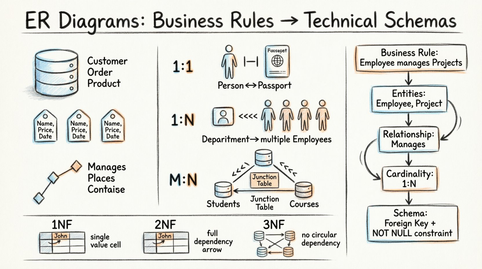
An ER diagram consists of three fundamental building blocks. Each block represents a specific aspect of how data is stored and related. Mastering these components allows for the construction of robust databases that align with organizational needs.
- Entities: These represent the objects or concepts about which data is collected. In a business context, these are often nouns such as Customer, Order, or Product. In the schema, entities become tables.
- Attributes: These describe the properties of an entity. Examples include Name, Price, or Date. Attributes become columns within the corresponding tables.
- Relationships: These define the associations between entities. A relationship indicates how instances of one entity connect to instances of another. In the database, relationships are often enforced via keys.
🔄 Translating Business Rules to Schema Elements
The most critical step in data modeling is the translation phase. Business stakeholders speak in terms of processes and policies. Engineers speak in terms of tables and constraints. The modeler must act as the interpreter between these two languages.
Consider a business rule: “A single employee can manage multiple projects, but a project must have at least one manager.” How does this become a schema?
- Identify the Entities: Employee and Project.
- Identify the Relationship: Manages.
- Define Cardinality: One employee to many projects (1:N). One project to at least one employee (1:1 or 1:N depending on interpretation).
- Enforce Optionality: The project must have a manager. This becomes a NOT NULL constraint on the foreign key.
This process requires careful analysis of the natural language provided by business users. Ambiguity is the enemy of data integrity. If a rule states “A customer can place orders”, does it imply they can place zero orders, or must they place at least one? This distinction changes the implementation of foreign keys.
📏 Cardinality and Optionality
Cardinality defines the number of instances of one entity that can or must be associated with each instance of another entity. It is the mathematical foundation of the relationship.
One-to-One (1:1)
This relationship occurs when a single record in one table relates to exactly one record in another. This is common when splitting tables for security or performance reasons, though it is less frequent in general business logic.
- Example: A person has one passport. A passport belongs to one person.
- Implementation: A foreign key in either table that references the primary key of the other.
One-to-Many (1:N)
This is the most common relationship type in relational databases. One record in Table A relates to multiple records in Table B. Table B holds the foreign key.
- Example: A department has many employees. An employee belongs to one department.
- Implementation: The Employee table contains a DepartmentID column.
Many-to-Many (M:N)
Two records in Table A can relate to multiple records in Table B, and vice versa. Direct implementation of this is not possible in standard relational schemas without an intermediate step.
- Example: Students enroll in Courses. A student takes many courses. A course has many students.
- Implementation: Create a junction table (associative entity) containing foreign keys from both parent tables.
| Relationship Type | Visual Notation (Concept) | Schema Implementation | Common Use Case |
|---|---|---|---|
| One-to-One (1:1) | |—| | Foreign Key in either table | Person ↔ Passport |
| One-to-Many (1:N) | |—<<< | Foreign Key in the ‘Many’ table | Department ↔ Employees |
| Many-to-Many (M:N) | <<<—<<< | Junction Table with two Foreign Keys | Students ↔ Courses |
🧩 Normalization Principles
Once the entities and relationships are defined, the schema must be normalized. Normalization is a systematic process of organizing data to reduce redundancy and improve data integrity. It involves decomposing tables into smaller, well-structured components.
First Normal Form (1NF)
Every column must contain atomic values. There should be no repeating groups or arrays within a single cell. Each row must be unique.
- Violation: A Skills column containing “SQL, Python, Java” in one cell.
- Correction: Split skills into a separate table linked by a relationship.
Second Normal Form (2NF)
The table must be in 1NF, and all non-key attributes must be fully dependent on the primary key. This eliminates partial dependencies.
- Scenario: A table combining Order and OrderItem where ProductName depends only on the ItemID, not the OrderID.
- Correction: Move ProductName to an Items table.
Third Normal Form (3NF)
The table must be in 2NF, and there should be no transitive dependencies. Non-key attributes should not depend on other non-key attributes.
- Scenario: A Customer table containing City and Country, where Country is determined by City.
- Correction: Create a Location table to hold City and Country data.
🛡️ Handling Constraints and Integrity
A schema is only as good as the rules that protect it. Constraints ensure that the data remains accurate and consistent over time.
Primary Keys
Every table must have a unique identifier. This ensures that no two rows are identical and allows for precise retrieval. In many systems, this is an auto-incrementing integer. In others, it might be a UUID or a natural key.
Foreign Keys
Foreign keys maintain referential integrity. They ensure that a record in the child table cannot exist without a corresponding record in the parent table. This prevents orphaned data.
- On Delete Cascade: If the parent is deleted, the child is deleted automatically.
- On Delete Restrict: Prevents deletion of the parent if children exist.
- On Delete Set Null: Deletes the parent but leaves the child record with a null foreign key.
Check Constraints
These enforce specific business logic directly within the database. Examples include ensuring a Price is greater than zero or a Start Date is before an End Date.
⚠️ Common Pitfalls in Data Modeling
Even experienced architects can overlook critical details. Being aware of common mistakes helps in designing more resilient systems.
- Over-Normalization: Splitting tables too aggressively can lead to complex joins that degrade query performance. Sometimes, denormalization is acceptable for read-heavy workloads.
- Ignoring Soft Deletes: Business rules often require retaining historical data. Deleting a record permanently removes the audit trail. A IsDeleted flag is often necessary.
- Assuming Uniqueness: Just because a business rule implies uniqueness (e.g., Email) does not mean the database enforces it. A unique constraint must be explicitly defined.
- Ignoring Time: Most business data has a temporal component. Recording When a record was created or updated is essential for auditing and debugging.
- Hardcoding Values: Using specific values in SQL queries instead of referencing lookup tables makes the system rigid and difficult to maintain.
🔄 The Iterative Design Process
Data modeling is rarely a linear process. It is iterative. The initial diagram is a hypothesis that must be tested against actual usage patterns and feedback.
- Conceptual Design: Focus on high-level entities and relationships. Ignore technical details like data types.
- Logical Design: Add attributes, define data types, and establish keys. Normalize the structure.
- Physical Design: Optimize for the specific database engine. Consider indexing strategies, partitioning, and storage.
- Review: Validate the model with stakeholders. Ensure it supports future business growth.
During the review phase, it is common to find that a relationship was misunderstood. For instance, a Many-to-Many relationship might actually be a hierarchy or a chain of One-to-Many relationships once deeper questions are asked. Flexibility in the design phase saves significant effort during the implementation phase.
📈 Scaling and Evolution
Schemas evolve. Requirements change. What fits today may not fit tomorrow. A well-designed ER diagram anticipates growth.
- Extensibility: Avoid hardcoding specific features into the schema. Use generic tables or attribute patterns (like EAV) where appropriate for highly dynamic requirements.
- Versioning: Keep track of schema changes. Migration scripts should be version-controlled alongside application code.
- Documentation: The diagram is the documentation. If the diagram does not match the database, trust the database but update the diagram immediately.
🔍 Conclusion on Structural Integrity
The quality of a database schema directly impacts the reliability of the applications that depend on it. An ER diagram is more than a drawing; it is a contract between the business logic and the technical infrastructure. By rigorously mapping business rules to technical schemas, ensuring proper normalization, and maintaining strict integrity constraints, we build systems that are resilient and efficient.
Focus on clarity in your diagrams. Use standard notation to ensure that any engineer can read the design. Prioritize data integrity over short-term performance gains, as fixing integrity issues later is far more costly than optimizing queries early. The goal is a schema that supports the business now and can adapt to it in the future.

