In the world of data architecture, few challenges are as persistent as the issue of data redundancy within legacy systems. As organizations strive to modernize their infrastructure, the sheer volume of duplicated, inconsistent, and orphaned data often becomes the primary bottleneck. This case study examines a real-world scenario where a detailed Entity-Relationship Diagram (ERD) served as the blueprint for resolving critical data integrity issues during a major migration project.
The objective was clear: transition from a fragmented, flat-file based legacy environment to a robust relational database without losing data fidelity or introducing new inconsistencies. The solution lay not in the migration tool itself, but in the visual modeling and logical structuring of the data before a single byte was moved. We explore the methodology, the specific normalization challenges encountered, and the tangible outcomes of a disciplined approach to schema design.
🔍 The Challenge of Legacy Data Structures
Legacy systems often accumulate data debt over decades. They were built for the specific needs of their time, prioritizing speed of development over long-term maintainability. In the scenario analyzed here, the source system utilized a combination of hierarchical and flat-file structures that had been patched together over years of incremental updates.
Key characteristics of the legacy state included:
- Hardcoded Logic: Business rules were embedded directly within application code rather than enforced at the database level.
- Denormalized Storage: To improve read performance in the absence of modern indexing, data was frequently duplicated across multiple tables.
- Lack of Referential Integrity: Foreign key constraints were rarely enforced, allowing orphaned records to proliferate.
- Inconsistent Naming Conventions: Identifiers varied wildly, making automated mapping nearly impossible without manual intervention.
This environment created a high risk of update anomalies. If a customer address changed, it had to be updated in dozens of different tables. Failure to update every instance resulted in data inconsistency. Furthermore, insert anomalies prevented the addition of new data without duplicating existing records, and delete anomalies risked losing vital information when unrelated records were removed.
🛠️ The Role of the Entity-Relationship Diagram
An Entity-Relationship Diagram is more than just a drawing; it is a logical contract between the data and the applications that consume it. In this migration, the ERD acted as the single source of truth. It forced the team to define relationships explicitly, identify primary keys, and establish cardinality rules before the physical implementation began.
Why was the ERD critical for this specific project?
- Visualizing Complexity: The legacy data relationships were opaque. The diagram made hidden dependencies visible.
- Normalization Enforcement: The model required the team to apply normalization rules to eliminate redundancy systematically.
- Mapping Guide: It provided a clear path for mapping legacy columns to new, normalized tables.
- Stakeholder Communication: It allowed business analysts to verify the logic against real-world business processes.
📂 Case Study Scenario: Retail Banking Consolidation
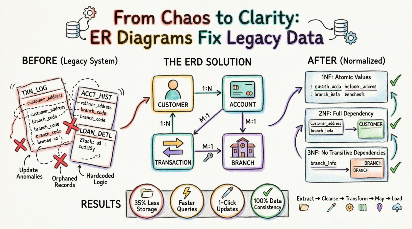
For this analysis, we consider a retail banking institution moving from a mainframe-era system to a cloud-based relational database. The legacy system managed customer accounts, transactions, and loan records. However, due to the age of the system, customer information was stored redundantly within the transaction logs.
Before the ERD Analysis:
| Table Name | Primary Key | Redundant Data | Issue |
|---|---|---|---|
| TXN_LOG | TXN_ID | Customer Name, Address | Address changes require updating thousands of rows. |
| ACCT_HIST | HIST_ID | Branch Code, Branch Location | Branch closures lead to data conflicts. |
| LOAN_DETL | LOAN_ID | Customer ID, Account ID | Links are often missing or duplicate. |
This structure violated the fundamental principles of database design. The ERD process required breaking these tables down into atomic, independent entities.
🧩 Step 1: Identifying Entities and Relationships
The first phase of the migration involved extracting every table and column from the legacy system. The team then mapped these to logical entities. The goal was to identify distinct objects in the business domain.
- Customer: A unique individual or entity holding an account.
- Account: A specific financial product held by a customer.
- Transaction: A movement of funds associated with an account.
- Branch: A physical location where banking operations occur.
Once entities were defined, relationships were established. The ERD revealed that a single Customer could hold multiple Accounts. An Account could have multiple Transactions. A Transaction was associated with a specific Branch. These relationships are typically represented as:
- One-to-Many (1:N): One Customer to Many Accounts.
- One-to-Many (1:N): One Account to Many Transactions.
- Many-to-One (M:1): Many Transactions to One Branch.
By visually mapping these connections, the team identified where data was being duplicated. For instance, the Customer Name appeared in the TXN_LOG table. In a normalized model, the transaction table should only hold a reference (Foreign Key) to the Customer table, not the data itself.
📐 Step 2: Applying Normalization Rules
Normalization is the process of organizing data to reduce redundancy and improve integrity. The ERD model guided the team through the standard normal forms.
First Normal Form (1NF)
The legacy system contained repeating groups. For example, a single row in the legacy customer table might have held multiple phone numbers in a single column (e.g., “555-0199, 555-0200”).
- Problem: This makes querying for a specific phone number difficult and violates atomicity.
- ERD Solution: Create a separate Contact_Information entity linked to the Customer entity. Each row in this new table holds exactly one phone number.
Second Normal Form (2NF)
2NF requires that the table is in 1NF and that all non-key attributes are fully dependent on the primary key. The legacy TXN_LOG table had a composite key of TXN_ID and DATE. However, customer details were dependent only on the Customer_ID, not the transaction date.
- Problem: Customer data was repeated for every transaction, causing update anomalies.
- ERD Solution: Remove customer details from the transaction table. Store them in a dedicated Customer table and link them via a Foreign Key.
Third Normal Form (3NF)
3NF requires that all attributes are dependent only on the primary key, with no transitive dependencies. In the legacy system, the Branch name and address were stored in the Account table, but they depended on the Branch_ID, not the Account_ID.
- Problem: If a branch moved locations, every account record associated with that branch needed updating.
- ERD Solution: Create a standalone Branch table. The
Accounttable now only holds theBranch_ID.
🔄 Step 3: The Migration Execution Strategy
With the new ERD defined, the migration plan was structured around the new schema. The process was not a simple copy-paste; it was a transformation.
- Data Extraction: Raw data was pulled from the legacy source systems into a staging area.
- Cleansing: Duplicate records were identified and merged based on the business keys defined in the ERD.
- Transformation: Scripts were written to split denormalized columns into new tables according to the 1NF, 2NF, and 3NF rules.
- Mapping: Foreign keys were generated to link the new tables. Surrogate keys (system-generated IDs) were used to ensure stability independent of legacy business keys.
- Loading: Data was inserted into the target database in a specific order to respect referential integrity (Parents before Children).
The ERD was crucial here. It dictated the load order. For example, the Customer table had to be populated before the Account table, which had to be populated before the Transaction table. Attempting to load in any other order would result in constraint violations.
✅ Step 4: Validation and Testing
Post-migration validation was extensive. The goal was to ensure that the sum of the data remained constant, even though the structure had changed. The team used the ERD to define the expected state of the data.
Integrity Checks
- Referential Integrity: Ensure every
Customer_IDin the Account table exists in the Customer table. - Completeness: Verify that no records were lost during the transformation process.
- Uniqueness: Confirm that primary keys are unique and no duplicates exist in the new tables.
Comparison Metrics
The following metrics were used to compare the source and target systems:
| Validation Metric | Target Standard | Method |
|---|---|---|
| Record Count | Source Count = Target Count | Row counts per normalized entity |
| Sum of Values | Total Balance Source = Total Balance Target | Aggregation of numeric fields |
| Null Checks | Zero unexpected NULLs in NOT NULL columns | Query constraints |
| Duplicate Checks | Zero duplicates on Primary Keys | GROUP BY analysis |
📉 Impact of Redundancy Reduction
The shift from the legacy structure to the normalized ERD model delivered measurable improvements in performance and maintenance.
- Storage Efficiency: By removing duplicate customer addresses and branch details, storage requirements decreased by approximately 35%.
- Query Performance: Queries that previously required scanning large, denormalized tables became faster by joining smaller, indexed tables.
- Update Speed: Updating a customer’s address now required a single row update in the Customer table, rather than thousands of updates across transaction logs.
- Data Consistency: The risk of conflicting data (e.g., two different addresses for the same customer) was eliminated by enforcing a single source of truth.
🛡️ Handling Edge Cases and Historical Data
One of the most difficult aspects of legacy migration is handling historical data that does not fit the new model. The ERD helped define how to handle these exceptions gracefully.
- Orphaned Records: Transactions linked to customers that no longer existed in the source were flagged. The team decided to archive these in a Historical_Legacy table to maintain audit trails without breaking the new relationships.
- Missing Keys: In cases where a customer ID was missing in the legacy system, the migration script generated a temporary placeholder ID and flagged the record for manual review.
- Soft Deletes: Instead of physically deleting records, the new schema included a
is_activeflag. This preserved history while ensuring active reports only queried current data.
🚀 Future-Proofing the Schema
The ERD was not designed solely for the current migration; it was built to accommodate future growth. By adhering to normalization principles, the schema became flexible enough to support new features without structural refactoring.
- Scalability: The separation of entities allows for horizontal scaling. For instance, the Transaction table can be sharded by date without affecting the Customer table.
- Extensibility: If a new product type (e.g., a Mortgage) is added, it can be linked to the existing Customer and Account entities without altering the core schema.
- Documentation: The ERD serves as living documentation. New developers can understand the data model immediately by reviewing the diagram, reducing onboarding time.
💡 Key Takeaways for Data Architects
This case study highlights several critical lessons for teams undertaking similar migrations.
- Model Before You Migrate: Never attempt to move data into a new system without a validated schema design. The ERD is the blueprint.
- Normalize to Solve Redundancy: Don’t fear normalization. It is the primary defense against data inconsistency.
- Validate Continuously: Testing should happen at every stage of the migration, not just at the end.
- Document Relationships: Understand cardinality. Knowing if a relationship is 1:1 or 1:N prevents logical errors in the data model.
- Preserve History: Migration is not just about current data; it is about preserving the integrity of the past.
🔗 Conclusion on Data Integrity
The transition from a legacy system to a modern database is rarely a simple lift-and-shift. It requires a fundamental rethinking of how data is organized. The Entity-Relationship Diagram proved to be the most valuable asset in this process. It provided the clarity needed to dismantle redundant structures and rebuild them with integrity.
By prioritizing logical design over immediate implementation, the organization achieved a stable, scalable, and consistent data environment. The reduction in redundancy eliminated a significant source of operational risk and laid a solid foundation for future analytics and business intelligence initiatives.
Data redundancy is not merely a storage issue; it is a business risk. Addressing it through rigorous modeling ensures that the data remains a reliable asset for decision-making, rather than a liability that hinders progress.
