Designing a robust data structure is the backbone of any successful software application. When projects move beyond simple prototypes and enter the intermediate phase, the complexity of data relationships increases significantly. This is where Entity Relationship Diagrams (ERDs) become critical tools for communication and planning. However, a well-drawn diagram does not guarantee a well-functioning database. Many developers fall into traps during the normalization process, leading to performance bottlenecks or data integrity issues later in development.
This guide explores the essential best practices for ER diagrams, specifically focusing on avoiding common normalization pitfalls. We will examine how to balance data integrity with performance, ensuring your schema remains maintainable as your project grows. Whether you are designing for a mid-sized e-commerce platform or a complex management system, these principles will help you build a foundation that stands the test of time.
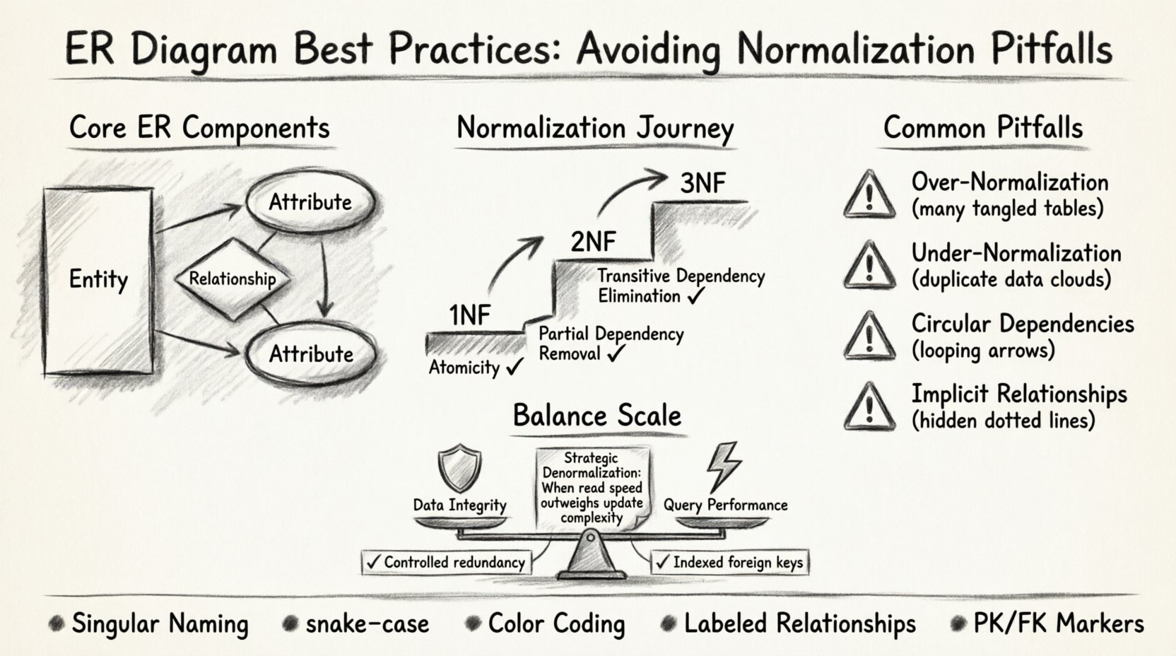
Understanding the Core Components of ER Modeling 🏗️
Before diving into normalization, it is essential to establish a clear understanding of the fundamental building blocks. An ER diagram visualizes the structure of a database through three primary elements:
- Entities: Represented as rectangles, these correspond to tables in the database. They describe objects of interest, such as Customer, Order, or Product.
- Attributes: Represented as ovals, these are the specific properties of an entity. For a Customer, attributes might include CustomerID, Name, and EmailAddress.
- Relationships: Represented as diamonds or connecting lines, these define how entities interact. A relationship indicates how data in one table connects to data in another.
In intermediate projects, the complexity often lies in the relationships. A simple one-to-one relationship is straightforward, but many-to-many relationships require careful handling to prevent redundancy. Visual clarity is just as important as logical correctness. A diagram that is cluttered or ambiguous can lead to misinterpretation by developers, resulting in schema inconsistencies during implementation.
The Normalization Process: A Deep Dive 🔍
Normalization is the systematic process of organizing data in a database to reduce redundancy and improve data integrity. While often taught as a rigid set of rules, it is actually a balancing act. In intermediate projects, the goal is not necessarily to reach the highest normal form, but to achieve the most efficient structure for the specific use case.
First Normal Form (1NF): The Foundation
The first step is ensuring atomicity. Every column in a table must contain only a single value. No repeating groups or arrays are allowed within a single cell.
- Check: Does every row have a unique identifier (Primary Key)?
- Check: Are all columns containing single values only?
- Example: A Products table should not have a column like Colors containing “Red, Blue, Green”. Instead, create a separate ProductColors table.
Second Normal Form (2NF): Eliminating Partial Dependencies
Once a table is in 1NF, it must also be in 2NF. This means eliminating partial dependencies. Every non-key attribute must depend on the whole primary key, not just part of it. This is crucial when dealing with composite keys.
- Rule: If a table has a composite primary key (A + B), every other column must depend on both A and B, not just A.
- Application: In an OrderDetails table with a composite key of OrderID and ProductID, the Quantity depends on both. However, ProductName depends only on ProductID. Moving ProductName to a Products table resolves this.
Third Normal Form (3NF): Removing Transitive Dependencies
3NF is the most common target for intermediate projects. It requires that no non-key attribute depends on another non-key attribute. All non-key attributes must depend directly on the primary key.
- Scenario: A Employee table has EmployeeID, DepartmentID, and DepartmentName.
- Issue: DepartmentName depends on DepartmentID, not EmployeeID.
- Solution: Move DepartmentName to a Departments table linked by DepartmentID.
Common Normalization Pitfalls in Intermediate Projects ⚠️
While normalization is powerful, applying it blindly can lead to significant issues. Intermediate projects often have unique requirements that demand a pragmatic approach. Below are the most frequent pitfalls encountered during schema design.
| Pitfall | Consequence | Solution |
|---|---|---|
| Over-Normalization | Too many tables and complex joins slow down read operations. | Denormalize Strategically: Combine tables for frequently accessed read-heavy data. |
| Under-Normalization | Data redundancy leads to update anomalies and wasted storage. | Enforce 3NF: Ensure non-key attributes do not depend on other non-key attributes. |
| Circular Dependencies | Foreign keys create loops that make data deletion difficult. | Audit Relationships: Review all foreign key constraints for cycles. |
| Implicit Relationships | Logic is hidden in application code rather than the schema. | Make it Explicit: Use foreign keys to enforce relationships in the database. |
Pitfall 1: The Performance Trap
One of the most common errors is striving for perfect normalization without considering query performance. In an intermediate project, you might have millions of records. A query that joins five different tables to retrieve a single user’s profile can be slow.
- Identify Hot Paths: Determine which queries run most frequently.
- Read vs. Write: If your application is read-heavy, consider denormalizing specific columns.
- Materialized Views: Use database views to store pre-computed results for complex aggregations.
Pitfall 2: Ignoring Cardinality Constraints
Cardinality defines the number of instances of one entity that can or must be associated with each instance of another entity. Failing to define this correctly in the ERD leads to data errors.
- One-to-One: A user has exactly one profile. (e.g., Users and UserProfiles).
- One-to-Many: A department has many employees. (e.g., Departments and Employees).
- Many-to-Many: A student can enroll in many courses, and a course has many students. This requires a junction table.
When designing the ER diagram, clearly mark these constraints. Ambiguity here often results in application bugs where the code assumes a relationship that does not exist in the database.
Visual Design Standards for Clarity 📊
A schema that works logically but is visually confusing is a liability. Intermediate projects often involve multiple developers working on different modules. The ER diagram must serve as a shared language.
- Consistent Naming Conventions: Use singular nouns for tables (e.g., Customer not Customers) and snake_case for column names (e.g., first_name).
- Logical Grouping: Group related entities together on the canvas. Place Order, OrderItem, and Product near each other.
- Color Coding: Use distinct colors for different types of entities (e.g., core tables vs. configuration tables) to aid quick recognition.
- Label Relationships: Never leave a line between tables without a label. Specify the type (e.g., “Has Many”, “Is Part Of”).
Consider the following checklist before finalizing your diagram:
- Are all primary keys clearly marked?
- Are foreign keys labeled consistently?
- Is the direction of the relationship clear (from parent to child)?
- Are optional vs. mandatory relationships distinguished?
Handling Many-to-Many Relationships 🔄
Many-to-many relationships are the most complex part of ER modeling. They cannot be represented by a single foreign key. Instead, they require an associative table, often called a junction table or bridge table.
When designing these tables, avoid creating simple placeholders. The junction table should hold meaningful data relevant to the relationship itself.
- Bad Design: A table with only UserID and GroupID.
- Good Design: A table with UserID, GroupID, JoinDate, and Role.
This approach allows you to store metadata about the relationship without violating normalization rules. It also enables queries like “Find all users who joined Group X after Date Y”.
Performance vs. Integrity Trade-offs 🛡️
There is no such thing as a perfect database schema. Every design decision involves a trade-off. In intermediate projects, the stakes are higher than in prototypes but lower than in enterprise systems. You must prioritize based on business needs.
Data Integrity
Normalization ensures integrity. If you normalize fully, you prevent duplicate data and ensure consistency. However, this comes at the cost of more complex joins.
- Foreign Keys: Use them to enforce referential integrity.
- Constraints: Use UNIQUE, NOT NULL, and CHECK constraints to validate data at the source.
Query Performance
Denormalization speeds up reads but complicates writes. If your application requires real-time analytics, you might need to duplicate data.
- Read Replicas: Consider a separate schema optimized for reporting.
- Caching: Use caching layers for frequently accessed normalized data.
- Indexing: Ensure foreign key columns are indexed to speed up join operations.
Maintenance and Evolution 📝
Database schemas are rarely static. As business requirements change, the ER diagram must evolve. A rigid adherence to a design created months ago can hinder progress.
- Version Control: Treat your schema definitions as code. Use migration scripts to track changes.
- Documentation: Keep the ER diagram synchronized with the actual database. An outdated diagram is worse than no diagram.
- Refactoring: Regularly review the schema. Are there tables that are no longer used? Are there columns that are always null?
When making changes, always consider the impact on existing data. Renaming a column might break application code. Adding a not-null constraint might fail on existing null values. Plan migrations carefully.
Conclusion on Schema Design ⚖️
Creating a high-quality ER diagram is an iterative process that requires technical knowledge and practical judgment. By understanding normalization principles and recognizing their limitations, you can avoid common pitfalls that plague intermediate projects. Focus on clarity, consistency, and the specific performance needs of your application.
Remember that the goal is not just to store data, but to retrieve it efficiently and maintain its accuracy over time. Regular reviews of your diagram against your actual queries will keep your project healthy. Apply these best practices, and your database architecture will support your application’s growth effectively.
- Review your relationships regularly.
- Balance normalization with performance needs.
- Document your decisions clearly.
- Validate your schema with real-world data scenarios.

