Creating a visual representation of a business process is a fundamental skill for anyone involved in operations, analysis, or systems design. Whether you are refining a workflow or documenting a legacy system, the ability to translate abstract ideas into structured diagrams is invaluable. Business Process Model and Notation (BPMN) provides the standard language for this task. It bridges the gap between business stakeholders and technical teams without relying on proprietary tools. This guide walks you through the foundational steps to begin modeling with BPMN from scratch, ensuring clarity, accuracy, and professional standards.
Why BPMN? The Value of Standardization 📊
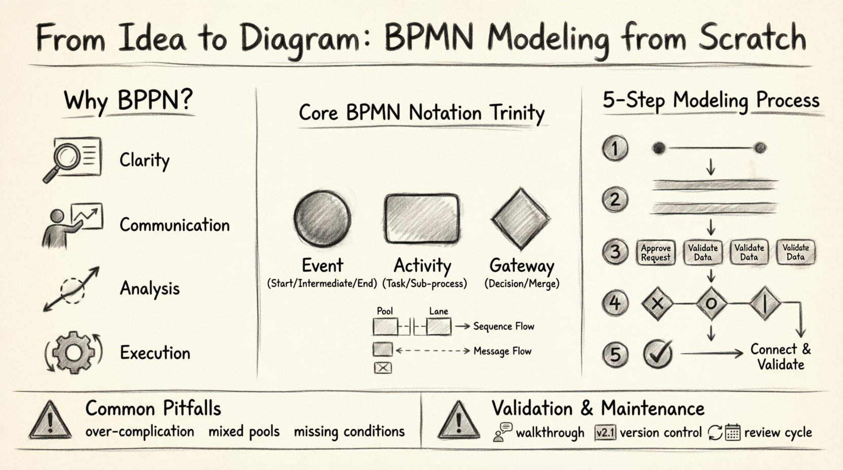
Before drawing the first symbol, it is crucial to understand why BPMN exists. In the past, organizations relied on ad-hoc flowcharts. These diagrams often used custom symbols that confused stakeholders who were not familiar with the specific drawing conventions. BPMN 2.0 standardized these symbols, creating a universal language. When a stakeholder sees a diamond shape, they immediately understand it represents a decision point. When they see a circle, they know it marks an event.
- Clarity: Eliminates ambiguity in process definitions.
- Communication: Allows business users to read the same diagram as developers.
- Analysis: Facilitates the identification of bottlenecks and inefficiencies.
- Execution: Provides a clear blueprint for automation engines.
Starting with BPMN ensures your diagrams are not just pictures, but functional documents that can be validated and potentially executed. It requires discipline and adherence to notation rules, but the payoff is a robust understanding of your organizational workflows.
Preparation: Before You Open Your Tool 🧠
Modeling is not merely about drawing lines; it is about thinking. The quality of your diagram depends heavily on the preparation work done before the first shape is placed on the canvas. Rushing into modeling without a clear scope often leads to complex, unreadable maps.
1. Define the Scope and Boundaries
Every process has a start and an end. A common mistake is to create a process that is too broad. For example, instead of modeling “Order Fulfillment,” model “Order Processing from Customer Click to Shipping Label.” Define the trigger that starts the process and the outcome that ends it. This boundary keeps the diagram focused.
2. Identify the Participants
Who is involved in this process? In BPMN, this is often visualized using pools and lanes. You need to know which departments, roles, or external entities are responsible for specific tasks. Creating a stakeholder map before modeling helps in structuring the swimlanes correctly.
3. Gather the Requirements
Do not rely on memory. Interview the people who perform the tasks. Ask them about exceptions, delays, and manual interventions. Documenting these details upfront prevents the need to backtrack later when you realize a step is missing.
Understanding the Core Notation ⚙️
BPMN is built on a set of graphical elements. Mastering these symbols is the first step to creating a valid diagram. While there are many elements, the core notation revolves around three main categories: Flow Objects, Connecting Objects, and Swimlanes.
The Trinity of Flow Objects
These are the building blocks that define the logic and flow of the process.
- Events: Represented by circles. They indicate something that happens. They can be Start (thin border), Intermediate (double border), or End (thick border).
- Activities: Represented by rounded rectangles. These are the work that is done. They can be Tasks (simple), Sub-processes (collapsed or expanded), or Call Activities.
- Gateways: Represented by diamonds. These control the flow of the process. They determine where the path splits or merges based on conditions.
Connecting Objects
These objects link the flow objects together to show the sequence.
- Sequence Flow: A solid line with an arrowhead. It shows the order in which activities are performed.
- Message Flow: A dashed line with a hollow arrow. It indicates communication between different pools or participants.
- Association: A dotted line. It links text annotations or data objects to flow objects.
Visual Reference: Common BPMN Symbols
| Category | Symbol Shape | Meaning |
|---|---|---|
| Event | Circle | Something that happens (Start, End, Intermediate) |
| Activity | Rounded Rectangle | Work performed (Task, Sub-process) |
| Gateway | Diamond | Decision point or merge point |
| Pool | Large Rectangle | Container for a participant (e.g., Organization) |
| Lane | Horizontal/Vertical Strip | Division within a pool (e.g., Department or Role) |
| Sequence Flow | Solid Line + Arrow | Order of execution |
| Message Flow | Dashed Line + Arrow | Communication between pools |
Step-by-Step Modeling Process 🛠️
Once you have your notation knowledge and preparation complete, you can begin the actual modeling. Follow this structured approach to ensure logical consistency.
Step 1: Sketch the High-Level Flow
Do not start with the smallest details. Begin with a high-level overview. Draw the Start Event, the End Event, and the major milestones in between. Use simple rectangles for tasks without worrying about the specific actors yet. This gives you the skeleton of the process.
Step 2: Add the Pools and Lanes
Now, introduce the participants. Create a Pool for each major entity involved. Inside the pool, draw Lanes to represent specific roles or departments. Move your high-level tasks into the appropriate lanes. This visualizes handoffs and responsibilities immediately.
Step 3: Detail the Tasks
Expand the high-level tasks into specific activities. If a task is complex, consider breaking it down into a Sub-process. This keeps the main diagram clean while allowing you to document detailed logic elsewhere. Ensure every task has a verb-noun label (e.g., “Verify Invoice” rather than “Invoice”).
Step 4: Insert Gateways and Logic
Where does the process split? Where does it converge? Use Gateways to represent these points. Be precise with the type of gateway:
- Exclusive Gateway (X): Only one path is taken (e.g., If/Else).
- Inclusive Gateway (O): One or more paths can be taken.
- Parallel Gateway (|): All paths are taken simultaneously.
Label the outgoing sequence flows with conditions. If there is no condition, the path is assumed to be taken. If there are multiple paths, ensure all possibilities are covered to prevent dead ends.
Step 5: Connect and Validate
Connect all elements using Sequence Flows. Check that every element has a connection unless it is an End Event. Ensure there are no dangling lines. At this stage, walk through the diagram logically. Start at the beginning and trace every possible path to the end. Does every path terminate? Are there loops that could run forever? This validation phase is critical.
Common Pitfalls to Avoid 🚧
Even experienced modelers make mistakes. Being aware of common errors can save you significant time during reviews.
- Over-complicating the Diagram: Trying to show every single step in one diagram makes it unreadable. Use Sub-processes to abstract detail. Keep the high-level view for management and the detailed view for execution.
- Mixing Pools and Lanes: Do not put communication between roles inside the same Pool. If two roles in the same department are communicating, use a Lane. If they are in different organizations, use a different Pool.
- Missing Conditions: Never leave a Gateway without a condition on the outgoing paths (except for the default flow). This creates ambiguity about which path the process will take.
- Ignoring Exceptions: Standard flows are easy, but exceptions are where the real work happens. Ensure you model what happens when an invoice is rejected, or a shipment is delayed. Use Intermediate Events to handle interrupts.
- Using Flowcharts as BPMN: Do not simply draw rectangles and diamonds and call it BPMN. Use the specific BPMN symbols. A rectangle is a Task, not a generic process step. A diamond is a Gateway, not just a decision.
Advanced Considerations for Scalability 📈
As your processes grow, the diagrams become larger. To maintain readability, consider these advanced strategies.
Data Objects
Processes manipulate data. Representing data objects (like documents or files) using the specific icon helps clarify what information is required or produced at each step. This is vital for system integration planning.
Text Annotations
Use Text Annotations to add context, rules, or links to external documents. These should be attached to the relevant element using an Association line. Do not clutter the main flow with text blocks.
Collaboration Diagrams
When multiple organizations interact, use Collaboration Diagrams. These involve multiple Pools connected by Message Flows. This visualizes the contract and communication boundaries between external parties, which is essential for supply chain or B2B processes.
Validation and Review Techniques 🔍
A diagram is only as good as its accuracy. Once the modeling is complete, you must validate it against reality.
- Walkthroughs: Conduct a session with the process owners. Ask them to trace the process on the screen. Do they agree with the path? Do they spot missing steps?
- Gap Analysis: Compare the as-is model with the desired state. Identify where the current process fails to meet business requirements.
- Logic Checks: Ensure there are no infinite loops and that all gateways are resolvable. Check that every path leads to an End Event.
Maintaining the Diagram 🔄
A process model is a living document. Business processes change over time due to new regulations, technology updates, or market shifts. A static diagram becomes a liability quickly.
Version Control
Always keep track of changes. When a process changes, create a new version of the diagram. Document the date, the author, and the reason for the change. This history is crucial for auditing and understanding why a process evolved.
Regular Reviews
Schedule periodic reviews of your process maps. Even if the process seems stable, a review can reveal optimization opportunities. Update the notation and labels to ensure they remain clear.
Conclusion
Starting to model with BPMN from scratch requires patience and adherence to standards. It transforms vague ideas into precise, actionable blueprints. By following the steps outlined here—preparing thoroughly, understanding the notation, modeling logically, and validating rigorously—you create diagrams that serve as effective communication tools. BPMN is not just about drawing; it is about understanding the flow of value within your organization. With practice, the notation becomes intuitive, and the diagrams become powerful assets for improvement and automation.

