


Business Process Model and Notation (BPMN) serves as the universal language for process modeling. However, a language without grammar rules leads to confusion. When teams create diagrams using BPMN 2.0 standards without adhering to strict notation rules, the resulting maps become ambiguous, difficult to automate, and prone to misinterpretation. Consistency is not merely an aesthetic preference; it is a functional requirement for successful process management.
This guide explores the essential notation rules required to maintain clarity and precision. By understanding the structural constraints of the standard, you ensure that your diagrams communicate intent clearly to stakeholders, developers, and business analysts alike.
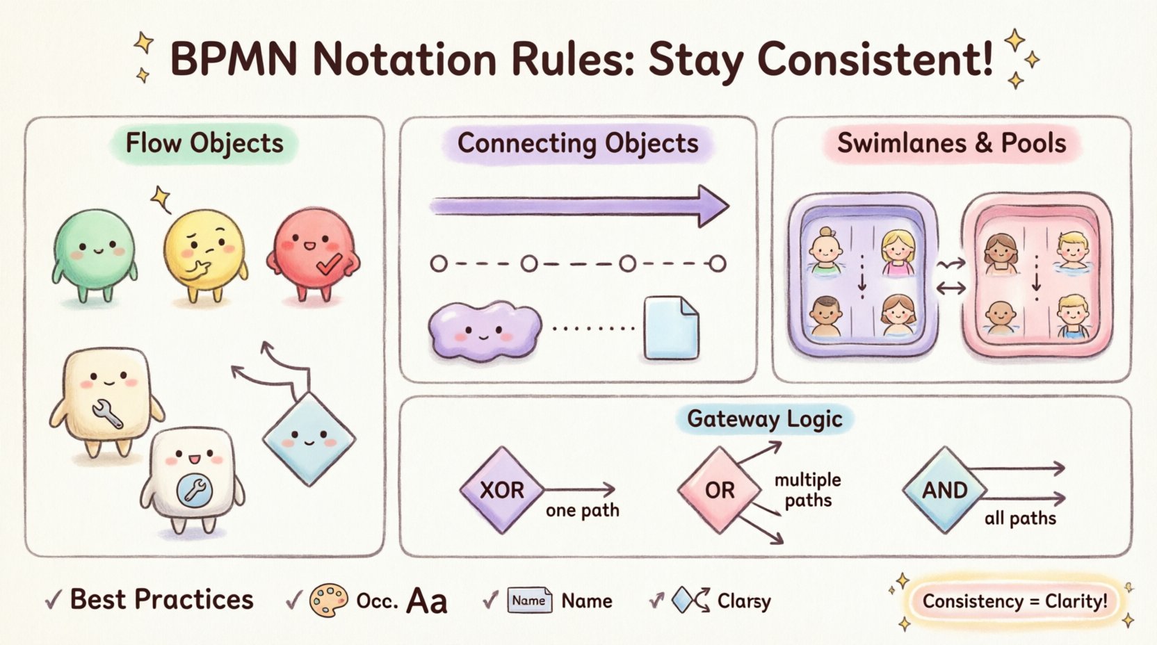
🏗️ The Foundation: Understanding Flow Objects
The core of any BPMN diagram lies in its flow objects. These shapes define the behavior and flow of the process. There are three distinct categories of flow objects that must be used correctly to maintain semantic integrity.
- Events: These are represented by circles. They indicate something that happens during the execution of a process. Events are strictly passive; they do not control the flow but rather signify a state change. They are categorized into:
- Start Events: Green circles indicating where the process begins.
- Intermediate Events: Yellow circles occurring between start and end events.
- End Events: Red circles signaling the termination of a process.
- Activities: Represented by rounded rectangles. These denote work that needs to be performed. They are subdivided based on granularity:
- Tasks: Atomic work units that cannot be broken down further within the context of the diagram.
- Sub-Processes: Complex activities that contain their own internal flow, allowing for abstraction.
- Call Activities: References to external processes or templates.
- Gateways: Diamond shapes that control the divergence and convergence of paths. They dictate the logic of the process flow.
🔗 Connecting Objects: The Logic of Movement
Flow objects are useless without connectors. These lines define the sequence and relationship between elements. Misusing connectors is one of the most common errors in process modeling.
Sequence Flows
Sequence flows represent the order of activities. They are depicted as solid lines with arrows. These flows indicate the direct order of execution.
- Sequence flows must always connect two flow objects.
- They cannot connect two events directly without an activity or gateway in between.
- They must not cross swimlanes unless explicitly modeling a hand-off via a message flow.
Message Flows
Message flows indicate the flow of messages between participants or between pools. These are rendered as dashed lines with open circle arrowheads.
- Message flows cannot exist within a single pool or lane. They require at least two distinct participants.
- They cannot connect to a gateway or activity directly; they must connect to an event (usually a message start or intermediate event).
- They represent communication across organizational boundaries or between different systems.
Associations
Associations link artifacts to flow objects or activities. They are shown as thin dotted lines.
- Use associations to attach data objects, annotations, or text to specific parts of the diagram.
- Do not use associations to define process logic or sequence.
🏊 Swimlanes and Pools: Organizing Responsibility
Pools and lanes provide a visual mechanism for organizing process elements by responsibility or organizational unit. This structure is critical for understanding who is doing what.
Pools
A pool represents a participant in a business process. It can represent an organization, a department, or a system.
- A single pool can contain multiple lanes.
- Different pools indicate separate participants. Interaction between pools requires message flows.
- Implicit pools are sometimes used to hide internal details, but explicit pools are preferred for clarity.
Lanes
Lanes subdivide a pool. They represent roles, departments, or specific systems within the participant.
- Elements within a lane belong to the responsibility of that lane.
- Sequence flows can cross lanes, but this indicates a hand-off or interaction between roles.
- Consistency dictates that all lanes within a pool should have the same width where possible to avoid visual clutter.
🧩 Artifacts: Adding Context
Artifacts add information to the diagram without affecting the flow of execution. They provide the necessary context for the reader.
- Data Objects: Represented by a document shape with a folded corner. They show data being created, used, or consumed. They should be linked via associations.
- Groups: Rectangles with a label at the bottom. They group elements visually but do not imply execution logic.
- Annotations: Text boxes with lines pointing to specific elements. These explain the “why” behind a process step.
🚦 Gateway Rules and Logic
Gateways are the decision points in a process. Using the correct gateway type is vital for accurate modeling of logic.
Inclusive vs. Exclusive Gateways
Confusion often arises between XOR and OR gateways. The distinction lies in the number of paths that can be taken.
- XOR Gateway (Exclusive): Only one outgoing path is taken based on the condition. If the condition is true, one path fires; if false, another fires. It is the standard choice for binary decisions.
- OR Gateway (Inclusive): Multiple outgoing paths can be taken simultaneously. This is used when multiple conditions can be true at once.
- AND Gateway (Parallel): All outgoing paths are taken. This is used to split a process into parallel tasks that run simultaneously.
📊 Common Violations and Best Practices
To maintain high-quality diagrams, modelers must avoid common pitfalls. Below is a summary of frequent errors and their corrections.
| Common Error | Why It Fails | Correct Approach |
|---|---|---|
| Connecting Sequence Flows to Events | Events are triggers, not steps. They cannot initiate a sequence directly. | Connect sequence flows to Activities or Gateways. |
| Using Message Flows inside a Pool | Message flows are for cross-participant communication. | Use Sequence Flows for internal communication within a pool. |
| Unclosed Gateways | Every split gateway should have a matching join gateway. | Ensure every split path converges correctly. |
| Overlapping Lines | Creates visual ambiguity regarding which element a flow connects to. | Route flows carefully to avoid crossing other lines. |
| Missing Labels on Gateways | Readers cannot understand the logic without conditions. | Label every outgoing path with a clear condition (e.g., “Yes/No”). |
🛡️ Establishing a Modeling Standard
Consistency requires governance. Without a defined standard, every modeler will interpret the rules differently. Establishing a style guide is the most effective way to ensure uniformity across an organization.
Key Components of a Style Guide
- Color Coding: Define specific colors for specific event types or process statuses. For example, always use red for end events to signal completion.
- Font Styles: Standardize font sizes for task names versus labels. Ensure readability across different screen sizes.
- Layout Rules: Define the preferred direction of flow (e.g., top-to-bottom or left-to-right). This reduces cognitive load for the reader.
- Naming Conventions: Create rules for naming tasks. Use action verbs (e.g., “Submit Application”) rather than nouns (e.g., “Application”).
- Gateway Logic: Specify the default gateway type for the organization. Most organizations default to XOR for efficiency unless parallelism is explicitly required.
🔍 Auditing and Maintenance
Process models are living documents. They require regular review to ensure they remain accurate and compliant with notation rules.
- Peer Review: Implement a mandatory review step where another analyst checks the diagram against the style guide.
- Automation Checks: Use validation tools to detect syntax errors, such as disconnected elements or missing labels.
- Version Control: Track changes to the model over time. This helps in understanding why a specific notation choice was made in the past.
- Feedback Loop: Allow end-users to report confusion. If a stakeholder asks, “What does this shape mean?”, the notation needs adjustment.
💡 The Impact of Consistency
Adhering to BPMN notation rules yields tangible benefits beyond simple aesthetics.
- Reduced Ambiguity: Clear rules eliminate the need for verbal explanations to interpret the diagram.
- Improved Automation: Consistent models are easier to convert into executable workflows. Ambiguous logic often breaks automated execution.
- Better Communication: Stakeholders from different departments can read the same diagram and understand the same process.
- Faster Onboarding: New employees can understand the process landscape more quickly when the notation is standardized.
🔄 Continuous Improvement
The standard evolves, and so should your understanding of it. BPMN 2.0 is the current dominant version, but extensions and best practices continue to develop. Stay updated on changes to the standard to ensure your models remain compliant.
Regularly schedule workshops to review the style guide. As the organization changes, the modeling rules may need to adapt to new business requirements or regulatory standards. This ensures that the documentation remains a reliable source of truth for the entire enterprise.
By treating BPMN notation as a disciplined practice rather than a creative exercise, you build a foundation for robust process management. The effort invested in consistency pays dividends in clarity, efficiency, and successful process execution.

")