


Business Process Model and Notation (BPMN) is the standard language for defining business processes. It bridges the gap between business stakeholders and technical developers. However, the precision required to create a valid model can be daunting for those new to the field. When a process diagram is inaccurate, it leads to confusion, implementation errors, and failed automation initiatives. Understanding the common pitfalls is the first step toward creating robust, executable process models.
This guide details ten frequent errors found in beginner-level BPMN diagrams. We will examine the technical implications of each mistake and provide actionable strategies to ensure your models remain compliant with the BPMN 2.0 specification. Accuracy here is not just about aesthetics; it is about ensuring that the process logic translates correctly to execution environments.
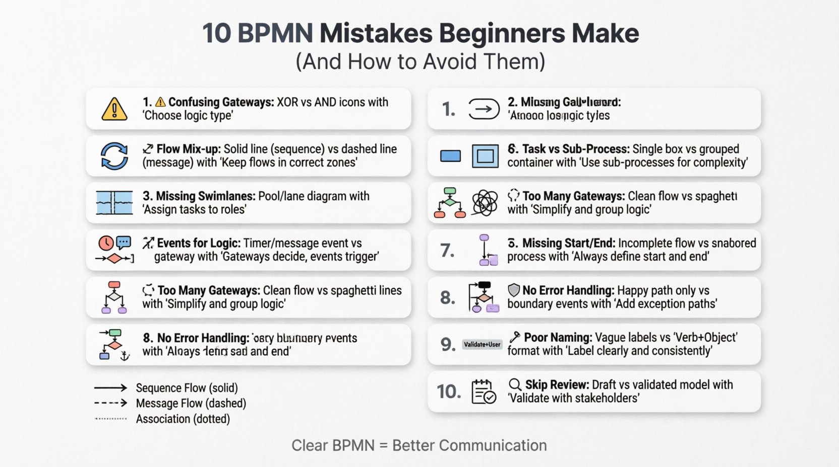
1. Confusing Gateways: Logic Flow Errors ⚠️
Gateways control the divergence and convergence of flows. They dictate whether a process splits into multiple paths or waits for multiple paths to merge. Beginners often confuse the Exclusive Gateway (XOR) with the Parallel Gateway (AND). This distinction is critical for process logic.
- Exclusive Gateway (XOR): Represents a decision point where only one path out of several is taken. It acts like an if-else statement in programming.
- Parallel Gateway (AND): Represents a synchronization point. All incoming paths must complete before the outgoing path begins. It acts like a parallel execution block.
When a beginner uses an XOR gateway where an AND gateway is needed, the process may skip necessary steps. Conversely, using an AND gateway for a simple decision creates a bottleneck, forcing the system to wait for non-existent parallel paths. Always verify the nature of the decision. Is it a choice (one option), or is it a requirement for all options (concurrency)?
2. Mixing Sequence and Message Flows 🔄
One of the most common visual errors is using a Sequence Flow (solid line) where a Message Flow (dashed line) is required. Sequence flows occur within a single pool or lane. They represent the order of execution. Message flows occur between pools. They represent communication between independent participants.
If you draw a message flow inside a single pool, the model becomes technically invalid. Similarly, drawing a sequence flow between pools suggests that one entity controls the other, which contradicts the concept of independent participants. Correct usage ensures that the diagram accurately reflects who is doing what and how information is exchanged.
Quick Reference: Flow Types
| Flow Type | Line Style | Location | Purpose |
|---|---|---|---|
| Sequence Flow | Solid Line | Within Pool/Lane | Execution Order |
| Message Flow | Dashed Line | Between Pools | Communication |
| Association | Dotted Line | Any | Linking Data/Text |
3. Ignoring Swimlanes (Pools and Lanes) 🏊
Pools represent participants, while lanes represent roles or departments within a participant. A process without lanes is often a “black box.” It hides the responsibility for each task. If a diagram shows a task but does not specify who performs it, the handoff between departments becomes ambiguous.
Beginners often collapse all tasks into a single pool to save space. While this simplifies the visual, it destroys the organizational context. A robust model must assign every task to a specific lane. This clarity is essential when the process is handed over to IT for implementation. Without lanes, developers cannot determine which system or user role should trigger the next step.
4. Using Tasks Instead of Sub-Processes 📦
A Task is an atomic unit of work. It cannot be broken down further within the diagram. A Sub-Process is a container that groups multiple tasks and flows. Beginners often try to fit an entire complex workflow into a single Task box.
This creates a diagram that is too dense to read. If a “Task” actually contains five steps, you should create a Sub-Process. Sub-processes allow for abstraction. You can show the high-level flow at the top level and drill down into the details at a lower level. This keeps the main diagram clean and focused on the major milestones rather than the granular steps.
5. Using Events for Logic Control 🚦
Events represent something that happens, such as a timer or a message. They are not decision points. A common mistake is using a Start Event or an Intermediate Event to control flow logic. For example, using an Intermediate Event to decide which path to take is incorrect.
Logic control belongs to Gateways. If a condition determines the path, use an Exclusive Gateway. If a timer determines when a path is taken, use a Timer Intermediate Event attached to a sequence flow leading to the next activity. Using events for logic confuses the reader about what is happening (the event) versus how the decision is made (the gateway).
6. Overcomplicating with Too Many Gateways 🧩
While gateways are powerful, excessive use makes a diagram unreadable. A process with ten gateways in a row creates a “spaghetti diagram.” It is difficult to trace the path from start to finish. This often happens when beginners try to model every possible exception or variation at the top level.
The solution is to group exceptions. If multiple paths lead to the same outcome, merge them. If a condition is complex, consider using an Inclusive Gateway (OR) instead of multiple Exclusive Gateways chained together. Simplify the visual path. If a section of logic is too complex, move it to a Sub-Process. Less is more when it comes to visual clarity.
7. Missing Start and End Events ⏹️
A BPMN diagram must have a clear beginning and a clear end. Omitting Start Events leaves the reader wondering how the process initiates. Omitting End Events leaves the process hanging, with no defined completion state.
Every valid process flow must begin with a Start Event and terminate with an End Event. Furthermore, if a process has multiple termination points (e.g., success, cancellation, timeout), each must have a corresponding End Event. This ensures that the lifecycle of the process is fully defined. Without these anchors, the diagram is incomplete and cannot be executed by a process engine.
8. Neglecting Error Handling 🛡️
Real-world processes do not always go smoothly. They encounter errors, exceptions, and timeouts. Beginners often model the “Happy Path” only. They show what happens when everything goes right. This is insufficient for robust automation.
You must include Error Events and Boundary Events. A Boundary Event is attached to an activity to catch errors that occur during that specific step. If a task fails, the flow should divert to an error handling routine rather than stopping abruptly. This includes defining what happens when a message is not received or a timeout occurs. Including these paths makes the model resilient and production-ready.
9. Inconsistent Naming and Labeling 🏷️
Labels should be concise and consistent. Using long sentences inside Task boxes makes the diagram cluttered. Conversely, using vague terms like “Do Stuff” or “Process Data” provides no value. Every task should start with a verb and include the object (e.g., “Review Application”).
Gateways should also be labeled. While the symbol indicates the logic type, the condition text (e.g., “Is Valid?”) clarifies the decision criteria. If you have multiple paths leaving a gateway, label each path with the condition required to take that path (e.g., “Yes” or “No”). Consistency in terminology helps stakeholders understand the model without needing a separate legend.
10. Skipping the Review and Validation Phase 🔍
The final mistake is assuming the first draft is the final draft. BPMN models require validation. They must be reviewed by the business stakeholders who own the process. If the model does not match reality, it is useless.
Validation involves walking through the process step-by-step with the subject matter experts. They can identify logical gaps, missing steps, or unrealistic constraints. Technical validation is also necessary to ensure the syntax is correct. Many modeling tools provide validation features to check for syntax errors. Never deploy a model without this final check. It is the difference between a theoretical diagram and a working specification.
Summary of Common Errors 📋
To aid in quick reference, here is a summary of the critical mistakes and their corrections.
| Mistake | Impact | Correction |
|---|---|---|
| Wrong Gateway Type | Incorrect Logic Flow | Use XOR for choices, AND for synchronization |
| Incorrect Flow Lines | Invalid Syntax | Use Sequence for internal, Message for external |
| No Swimlanes | Missing Ownership | Assign every task to a specific lane |
| Task vs Sub-Process | Dense Diagram | Use Sub-Processes for complex logic |
| Events for Logic | Confusing Structure | Use Gateways for decisions, Events for triggers |
| Too Many Gateways | Spaghetti Diagram | Group logic, use Inclusive Gateways |
| Missing Start/End | Incomplete Process | Ensure every flow has defined start and end points |
| No Error Handling | Fragile Process | Add Boundary Events for exceptions |
| Poor Naming | Low Clarity | Use Verb + Object format for tasks |
| No Review | Incorrect Model | Validate with stakeholders before finalizing |
The Importance of Standardization 📐
Beyond avoiding mistakes, adhering to the BPMN 2.0 standard ensures interoperability. Different organizations use different tools to model and execute processes. A standardized model can be imported from one platform to another without losing its structural integrity. Deviating from the standard notation often breaks this compatibility. It forces teams to rewrite logic when switching tools.
Consistency also aids in training. When new team members join, they can read the diagrams without needing a specialized decoder ring. If the notation is standard, the learning curve is reduced. This is a long-term investment in the organization’s knowledge base. It allows the process documentation to remain valid as personnel change over time.
Deep Dive: Sequence Flow vs Message Flow 📉
Let us expand on the distinction between Sequence and Message flows, as this is the most frequent source of technical errors. A Sequence Flow implies direct control. When one task finishes, the sequence flow immediately triggers the next task. There is no intermediary communication protocol involved. It is a direct handoff.
A Message Flow implies an exchange of information. One participant sends a message, and the other receives it. This often involves asynchronous behavior. The sender does not necessarily wait for the receiver to process the message immediately. In a diagram, a Message Flow must always start and end with an Event (usually a Send or Receive Task, or a Message Start/End Event). It cannot start directly from a Task or a Gateway. This rule ensures that the communication boundary is respected.
If you model a Message Flow incorrectly, a process engine may not be able to interpret the interaction. It might try to execute a task that does not exist in the receiving pool. This results in runtime errors. Always ensure that Message Flows connect Event shapes. This visual cue tells the engine that an asynchronous message exchange is occurring, not a direct execution trigger.
Handling Exceptions Gracefully 🛠️
Exception handling is often the most overlooked aspect of process modeling. In a perfect world, every task succeeds on the first try. In the real world, systems fail, data is invalid, and users make mistakes. A model that does not account for this is a fantasy.
Boundary Events allow you to attach error handling directly to a specific task. If a task is a database update, a Boundary Event can catch a “Connection Timeout” error. The flow then diverts to a notification task or a retry logic loop. This keeps the main flow clean while ensuring errors are managed. Do not rely on a single End Event for all errors. Define specific error paths for critical failures.
Furthermore, consider the difference between a User Task error and a System Task error. A User Task might have a “Cancel” option, which requires a specific End Event. A System Task might fail silently or crash. These require different modeling approaches. Understanding the nature of the task helps you choose the correct error handling mechanism.
Conclusion on BPMN Mastery 🎯
Creating accurate BPMN diagrams requires attention to detail and a solid understanding of the specification. By avoiding the ten mistakes outlined above, you ensure your models are clear, logical, and executable. The goal is not just to draw a picture, but to create a specification that can be understood by humans and machines alike.
Focus on the logic. Ensure the flow is unambiguous. Verify that the notation is standard. Regularly validate your work with stakeholders. Over time, these practices become second nature. A well-constructed process model is a valuable asset that drives efficiency and reduces operational risk. Take the time to get it right the first time, and your process documentation will serve your organization for years to come.
Remember that BPMN is a tool for communication. If the diagram is confusing to you, it will be confusing to the developers and the business users. Clarity is the ultimate metric of success in process modeling. Strive for precision in every symbol and every line. This discipline separates a hobbyist from a professional process architect.

